


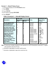
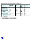
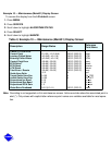
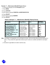
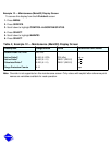
Note: This screen provides the means to generate alert messages based on exceeding the ‘‘Temp’’ thresh-
old for each point listed. If the ‘‘Enable’’ is set to 1, a value above the ‘‘Temp’’ threshold shall generate
an alert message. If the ‘‘Enable’’ is set to 2, a value below the ‘‘Temp Alert’’ threshold shall generate
an alert message. If the ‘‘Enable’’ is set to 0, alert generation is disabled. If the “Enable” is set to 3, a
value above the “Temp” threshold will generate an alarm. If the “Enable” is set to 4, a value below the
“Temp” threshold will generate an alarm.
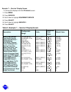
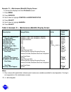
OPTIONS BOARD 2
20 mA POWER CONFIGURATION
External = 0, Internal = 1
SPARE 1 20 mA Power Source
SPARE 2 20 mA Power Source
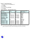
SPARE ALERT ENABLE
Disable = 0, 1 = High Alert, 2 = Low Alert,
3 = High Alarm, 4 = Low Alarm
Temp = Alert Threshold
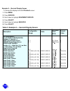
Spare Temp 4 Enable
Spare Temp 4 Alert
Spare Temp 5 Enable
Spare Temp 5 Alert
Spare Temp 6 Enable
Spare Temp 6 Alert
Spare Temp 7 Enable
Spare Temp 7 Alert
Spare Temp 8 Enable
Spare Temp 8 Alert
Spare Temp 9 Enable
Spare Temp 9 Alert
0, 1
0, 1
0-4
–40-245 (–40-118)
0-4
–40-245 (–40-118)
0-4
–40-245 (–40-118)
0-4
–40-245 (–40-118)
0-4
–40-245 (–0-118)
0-4
–40-245 (–40-118)
DEG F (DEG C)
DEG F (DEG C)
DEG F (DEG C)
DEG F (DEG C)
DEG F (DEG C)
DEG F (DEG C)
sp1
20 ma
sp2
20 ma
spr4
en
spr4
al
spr5
en
spr5
al
spr6
en
spr6
al
spr7
en
spr7
al
spr8
en
spr8
al
spr9
en
spr9
al
0
0
0
245 (118)
0
245 (118)
0
245 (118)
0
245 (118)
0
245 (118)
0
245 (118)
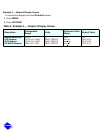
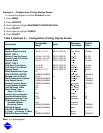
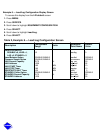
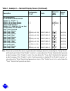
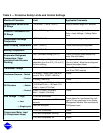
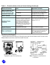
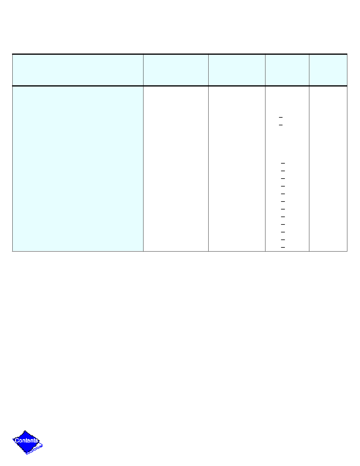
Table 2, Example 8 — Service2 Display Screen (Continued)
Description
Configurable
Range
Units
Reference
Point
Name
Default
Value