


points side to side in a similar manner when checking for misalignment in plan.
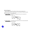
Measurement
— With dial set at zero in the top position, rotate the shaft to which the
indicator is attached 180 degrees. If the dial reading is plus, the shaft on which the button rests
is low. If the reading is minus, the shaft on which the button rests is high.
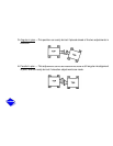
Never accept a single reading. Look for repeatability. Rotate the shaft several times to see if
the reading remains the same. It is good practice to reverse the procedure and read from zero
at the bottom.
Always rotate the shafts in the same direction when taking readings. Backlash in the coupling
teeth could cause some differences.
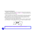
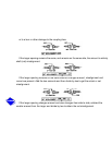
Adjustment
— Divide the total indicator reading by two to obtain the exact amount of shaft
offset. As illustrated in Figure 42, the indicator will read the total of A plus B but the required
shaft adjustment is only half of this as indicated by C.
Add or remove identical amounts of shims at all footings to bring the shaft to the proper
elevation. Tighten all the holddown bolts and recheck the readings. Parallel alignment must be
within .002 TIR.
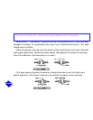
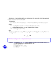
To correct parallel misalignment in plan, use a screw jack and dial indicator as shown in
Figure 42. With a front holddown bolt as the pivot, move the rear of the equipment over. Then,
with the rear holddown bolt
on the same side
acting as the pivot, move the front end of the
equipment over by the same amount.