


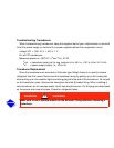

Notes on Module Operation
1.
The machine operator monitors and modifies configurations in the microprocessor through
the 4 softkeys and the LID. Communication with the LID and the PSIO is accomplished
through the CCN bus. The communication between the PSIO, SMM, and both 8-input
modules is accomplished through the sensor bus, which is a 3-wire cable.
On sensor bus terminal strips, Terminal 1 of PSIO module is connected to Terminal 1 of
each of the other modules. Terminals 2 and 3 are connected in the same manner. See
Figure 49, Figure 50, Figure 51, Figure 52, and Figure 53. If a Terminal 2 wire is connected
to Terminal 1, the system does not work.
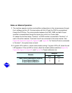
2.
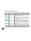
If a green LED is solid on, check communication wiring. If a green LED is off, check the red
LED operation. If the red LED is normal, check the module address switches (Figure 49,
Figure 50, Figure 51, Figure 52, and Figure 53). Proper addresses are:
Module
Address
SW1 SW2
SMM (Starter Management Module)
8-input Options Module 1
8-input Options Module 2
3
6
7
2
4
2