


17/19EX Physical Data and Wiring Schematics
Table 10, Table 11, Table 12, Table 13, Table 14, Table 15, Table 16, Table 17, Table 18,
Figure 54, Figure 55, Figure 56, Figure 57, Figure 58, Figure 59, Figure 60, Figure 61, and
Figure 62 provide additional information regarding compressor fits and clearances, physical and
electrical data, and wiring schematics for operator convenience during troubleshooting.
Click here for Figure 54 — Model Number Nomenclature for Compressor Size
(See Figure 1 also)
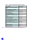
Click here for Table 10 — 17/19EX Heat Exchanger, Economizer/Storage Vessel,
Piping, and Pumpout Unit Weights
Click here for Table 11 — Additional Condenser Weights
Click here for Table 12 — Compressor/Motor/Suction Elbow Weights