


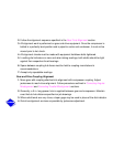
Correcting Angular Misalignment
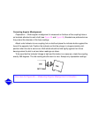
Preparation
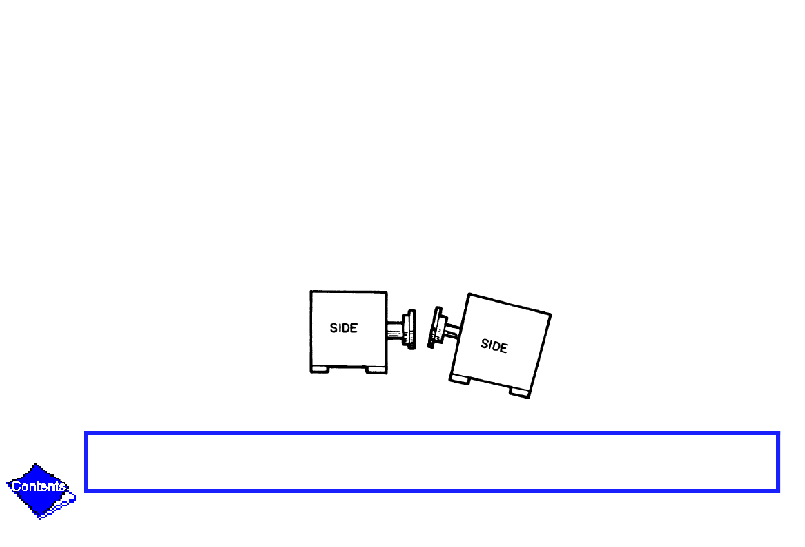
— Shaft angular misalignment is measured on the face of the coupling hubs or
on brackets attached to each shaft (see Figure 38 and Figure 39). Brackets are preferred since
they extend the diameter of the face readings.
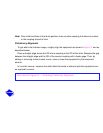
Attach a dial indicator to one coupling hub or shaft and place the indicator button against the
face of the opposite hub. Position the indicator so that the plunger is at approximately mid-
position when the dial is set to zero. Both shafts should be held tightly against their thrust
bearings when the dial is set and when readings are taken.
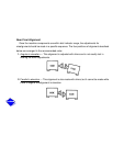
To be sure that the indicator linkage is tight and the button is on securely, rotate the coupling
exactly 360 degrees. The dial reading should return to zero. Accept only repeatable readings.
Click here for Figure 38 — Measuring Angular Misalignment in Elevation