


2. Follow the alignment sequence specified in the Near Final Alignment section.
3. All alignment work is performed on gear and drive equipment. Once the compressor is
bolted in a perfectly level position and is piped to cooler and condenser, it must not be
moved prior to hot check.
4. All alignment checks must be made with equipment holddown bolts tightened.
5. In setting dial indicators on zero and when taking readings, both shafts should be tight
against their respective thrust bearings.
6. Space between coupling hub faces must be held to coupling manufacturer’s
recommendations.
7. Accept only repeatable readings.
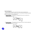
Gear and Drive Coupling Alignment
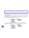
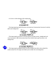
1. Move gear with coupling attached into alignment with compressor coupling. Adjust
jackscrews to reach close alignment. Follow procedures outlined in Correcting Angular
Misalignment and Correcting Parallel Misalignment sections.
2. Generally, a 5-in. long spacer hub is supplied between gear and compressor. Maintain
exact hub-to-hub distance specified on job drawings.
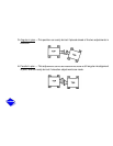
3. Where shaft ends are very close, a taper gage may be used in place of the dial indicator.
4. Get drive alignment as close as possible by jackscrew adjustment.