


Model 500/600
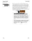
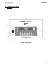
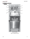
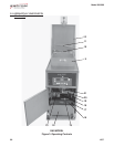
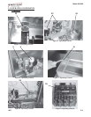
The images at the end of this section, identify all the operator
controls and the major components of the pressure fryer.
1207 3-3
Fig. Item Description Function
No. No.
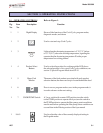
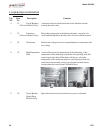
2 1 Lid Latch A spring loaded latch that provides a positive latch to hold the lid
closed; this latch, along with the spindle assembly and lid gasket,
provides a pressure sealed frypot chamber
2 2 Lid Limit Stop A threaded adjustable collar used to obtain the proper
tightness between the lid gasket and the frypot rim; done by
controlling the number of clockwise rotations of the spindle
2 3 Solenoid Valve An electromechanical device that causes pressure to be held in the
frypot; the solenoid valve closes at the beginning of the Cook Cycle
and is opened automatically by the controls at the end of the Cook
Cycle; if this valve becomes dirty or the teflon seat nicked, pressure
won’t build and must be repaired
2 4 Spindle An assembly that is tightened after the lid is latched, and applies
Assembly pressure to the top of the lid; the lid gasket then applies pressure
against the frypot rim; after building one pound of internal pressure,
the lid liner pushes a locking pin up into the locking collar, prevent-
ing the spindle from being turned while the frypot is pressurized
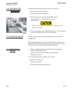
2 5 Safety Relief
Valve Ring
DO NOT PULL THIS RING. SEVERE BURNS FROM
THE STEAM WILL RESULT.
2 6 Safety Relief This is an ASME approved spring loaded valve, set at 14.5 psi;
Valve if the deadweight assembly is clogged, this safety valve releases
excess pressure, keeping the frypot chamber at 14.5 psi
(999 mbar) if this occurs, turn the main power switch to OFF to
release all pressure from the frypot
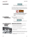
If safety relief valve activates, turn main power switch to
the OFF position. To avoid serious burns and injuries,
have fryer serviced before next use.
3-2. OPERATING COMPONENTS