


Technical Information
G600 & G800 Electronic Dishwashers
G600 &G800 Electronic Dishwashers – List of Figures
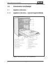
1-1: Appliance Overview - Typical Integrated Model...................................9
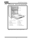
1-2: Appliance Overview – Typical Fully Integrated (Vi) Model .................10
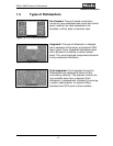
1-3: Pre-Finished Dishwasher...................................................................13
1-4: Integrated Dishwasher .......................................................................13
1-5: Fully Integrated ..................................................................................13
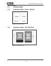
1-6: Dishwasher Widths ............................................................................14
1-7: Dishwasher Heights ...........................................................................14
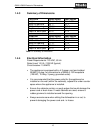
1-8: Data Tag Locations and Information ..................................................17
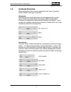
1-9: Component Overview – Novotronic & Touchtronic Series .................18
1-10: Component Overview – Incognito (Vi) Series ....................................19
4-1: Dispenser Assembly ..........................................................................25
4-2: Cavity Style Heater Element ..............................................................27
4-4: Heater Circuit.....................................................................................29
4-5: Filter Assembly ..................................................................................31
4-6: WaterProof System Connection.........................................................33
4-7: Water Intake Circuit............................................................................35
4-8: Flowmeter Assembly Components (External Flowmeter Shown) ......36
4-9: Water Intake System Equipped With Integrated Flowmeter...............37
4-10: Water Hardness Selector...................................................................38
4-11: Water Path with Integrated Flowmeter...............................................39
4-12: Water Inlet Mixer................................................................................40
4-13: Water Hardness Mixer Solenoid ........................................................41
4-14: Water Softener...................................................................................43
4-15: Components for the Condenser Drying System.................................47
4-16: Control Valve .....................................................................................48
4-17: Heater Pressure Switch – Contact Positions and Current Paths........50
4-18: Water Intake / Level Switch Circuit.....................................................51
4-19: Circulation Pump & Top Solo Valve. ..................................................53
4-20: Turbidity Sensor (ECO Sensor) .........................................................54
5-1: Locking Plate .....................................................................................57
5-2: Seal Fitting Plan.................................................................................57
5-3: Side Panels and Cabinet....................................................................58
5-4: Side View, Door with Bracket.............................................................59
5-5: Cover Plate ........................................................................................60
5-6: Plinth area with Connecting Strip.......................................................61
5-7: Basket Guide .....................................................................................62
5-8: Bolt and Retaining Clip.......................................................................62
5-9: Basket Guide Stopper........................................................................63
5-10: Stopper removal.................................................................................63
6