


Installation
8
Ventilation
On gas models the installation of a proper ventila-
tion system cannot be over emphasized. This sys-
tem removes unwanted vapors and products of
combustion from the operating area.
This oven may be vented using either:
D
A mechanically driven, canopy type, exhaust
hood, or
D
A direct flue arrangement.
U.S. and Canadian installations
Refer to your local ventilation codes. In the ab-
sence of local codes, refer to the National ventila-
tion code titled, “Standard for the Installation of
Equipment for the Removal of Smoke and Grease
Laden Vapors from Commercial Cooking Equip-
ment”, NFPA-96-Latest Edition.
Australia and general export installations
Installation must conform with Local and National
installation standards. Local installation codes
and/or requirements may vary. If you have any
questions regarding the proper installation and/or
operation of your Blodgett oven, please contact
your local distributor. If you do not have a local dis -
tributor, please call the Blodgett Oven Company at
0011-802-860-3700.
WARNING:
Failure to properly vent the oven can be
hazardous to the health of the operator
and may result in operational problems,
unsatisfactory baking and possible dam-
age to the equipment.
Damage sustained as a direct result of im -
proper ventilation will not be covered by
the manufacturer’s warranty.
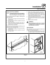
CANOPY TYPE EXHAUST HOOD
A mechanically driven, canopy type exhaust hood
is the preferred method of ventilation.
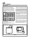
The hood should be sized to completely cover the
equipment plus an overhang of at least 6” (15 cm)
on all sides not adjacent to a wall. The distance
from the floor to the lower edge of the hood should
not exceed 7’ (2.1m).
The total makeup and exhaust air requirements for
hood capacity should be approximately 30 CFM
(.85 m
3
) for each oven section.
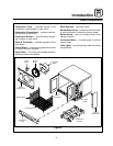
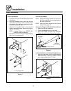
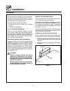
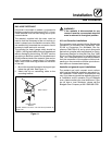
Installing the canopy hood draft diverter
Ovens ordered for hood venting are supplied with
a draft diverter. Install the draft diverter as follows:
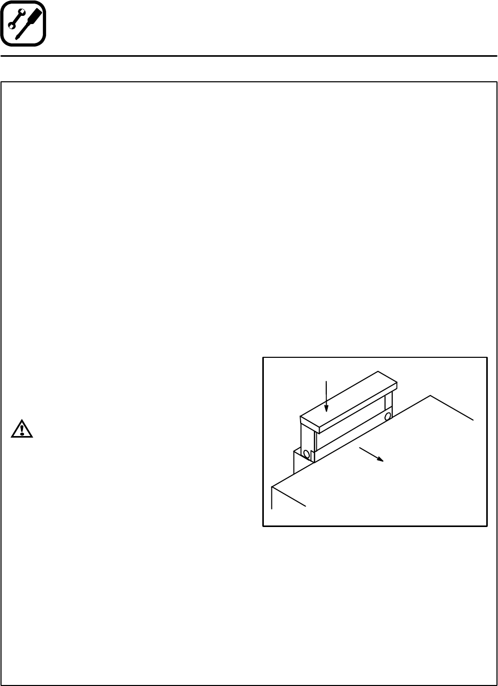
1. Place the diverter over the flue connector with
the open area facing the front of the oven. See
Figure 8.
2. Secure both ends with the sheet metal screws
provided.
Front of
Oven
Draft Diverter
Figure 8