


vi
T309
LIST OF ILLUSTRATIONS
FIGURE NUMBER Page
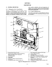
Figure 2-1 Refrigeration Unit -- Front Section 2-1...............................................
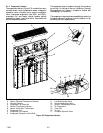
Figure 2-2 Evaporator Section 2-2............................................................
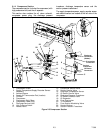
Figure 2-3 Compressor Section 2-3...........................................................
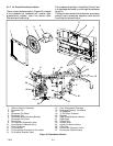
Figure 2-4 Condenser Section 2-4............................................................
Figure 2-5 Control Box Section 2-5...........................................................
Figure 2-6 Refrigeration Circuit Schematic -- Standard Operation 2-10................................
Figure 2-7 Refrigeration Circuit Schematic -- Economized Operation 2-11.............................
Figure 2-8 Refrigeration Circuit Schematic -- Unloaded Operation 2-11...............................
Figure 3- 1 Temperature Control System 3-1...................................................
Figure 3- 2 Key Pad 3-2....................................................................
Figure 3- 3 Display Module 3-2..............................................................
Figure 3- 4 Control and Expansion Modules 3-3.................................................
Figure 3- 5 Standard Configuration Download Report 3-9.........................................
Figure 3- 6 Data Reader 3-11.................................................................
Figure 4-1 Make Up Air Flow Chart 4-1.......................................................
Figure 4-2 Controller Operation -- Perishable Mode 4-4...........................................
Figure 4-3 Controller Operation -- Frozen Mode 4-5..............................................
Figure 4-4 Perishable Mode 4-5..............................................................
Figure 4-5 Perishable Mode Heating 4-6.......................................................
Figure 4-6 Frozen Mode 4-6................................................................
Figure 4-7 Defrost 4-7.....................................................................
Figure 6-1 Service Valve 6-1................................................................
Figure 6-2 Suction Service Valve 6-1.........................................................
Figure 6-3 Manifold Gauge Set 6-1...........................................................
Figure 6-4 R-134a Manifold Gauge/Hose Set 6-2................................................
Figure 6-5. Refrigeration System Service Connections 6-3.........................................
Figure 6-6. Compressor Service Connections 6-4................................................
Figure 6-7 Compressor Upper Mounting 6-6....................................................
Figure 6-8 Compressor Lower Mounting 6-6...................................................
Figure 6-9 High Pressure Switch Testing 6-8...................................................
Figure 6-10 Thermostatic Expansion Valve Bulb 6-9.............................................
Figure 6-11 Evaporator Expansion Valve 6-9...................................................
Figure 6-12 Hermetic Thermostatic Expansion Valve Brazing Procedure 6-10..........................
Figure 6-13 Economizer Expansion Valve 6-10..................................................
Figure 6-14. Unloader Solenoid Valve 6-11.....................................................
Figure 6-15. Oil Return S olenoid Valve (ORV), Economizer Solenoid Valve (ESV),
Liquid Injection Solenoid Valve (LIV) 6-11...........................................
Figure 6-16. Evaporator Fan Assembly 6-12.....................................................
Figure 6-17 Suction Modulation Valve (SMV) 6-13...............................................
Figure 6-18 Controller Section of the Control Box 6-15............................................
Figure 6-19 Sensor Types 6-16...............................................................
Figure 6-20 Typical S ensor and Cable Splice 6-17................................................
Figure 6-21 Supply Sensor Positioning 6-18.....................................................