


3-15
T -309
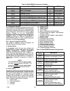
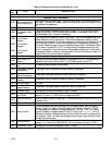
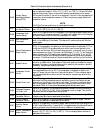
Table 3-5 Controller Function Codes (Sheet 2 of 3)ff
Cd22 Compressor S tate The status of the compressor is displayed (Off, On).
Cd23 Evaporator Fan Displays the current evaporator fan state (high, low or off).
Cd24
Controlled
Atmosphere State
Not used in this application
Cd25
Compressor Run
Time Remaining
Until Defrost
This code displays the time remaining until the unit goes i nto defrost (in tenths of
an hour). This value is based on the actual accumulated compressor running time.
Cd26
Defrost Temperature
Sensor R eading
Defrost temperature sensor reading is displayed.
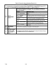
Configurable Functions
NOTE
Function codes Cd27 through Cd37 are user-selectable functions. The operator can change the value of
these functions to meet the operational needs of the container.
Cd27
Defrost Interval
(Hours)
The defrost interval is the time between defrost cycles. Five selectable values are
available: 3, 6, 9, 12 or 24 hours. The factory default value is 12 hours. Follow-
ing a start--up or after termination of a defrost, t he time will not begin counting
down until the defrost temperature sensor (DTS) reading falls below set point. If
the reading of DTS rises above set point any time during the timer count down,
the interval is reset and the countdown begins over. If DTS fails, alarm code
AL60 is activated and control switches over to the the return temperature sensor.
The controller will act in the same manner as with the DTS except the return tem-
perature sensor reading will be used.
Defrost Interval Timer Value (Configuration variable CnF23): If the software is
configured to “SAv” (save) for this option, then the value of the defrost interval
timer will be saved at power down and restored at power up. This option prevents
short power interruptions from resetting an almost expired defrost interval, and
possibly delaying a needed defrost cycle.
NOTE
The defrost interval timer counts only during compressor run time.
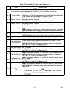
Cd28
Temperature Units
(_Cor_F)
This code determines the temperature units (_Cor_F) which will be used for all
temperature displays. The user selects _Cor_F by selecting function code Cd28
and pushing the ENTER key. The factory default value is Celsius units.
NOTE
This function code will display “--- --- --- --- --- “ if Configuration Variable
CnF34 is set to _F.
Cd29
Failure Action
(Mode)
If all of the control sensors are out of range (alarm code AL26) or there is a probe
circuit calibration failure (alarm code AL27), the unit will enter the shutdown
state defined by this setting. The user selects one of four possible actions as fol-
lows:
A -- Full Cooling (compressor is on, economized operation. SMVsubject to pressure
and current limit.)
B -- Partial Cooling (Compressor is on, standard operation. SMV subject to pressure
and current limit.)
C -- Evaporator Fan Only (Compressor is off, evaporator fans on high speed, not ap-
plicable with frozen set points.
D -- Full System Shutdown -- Factory Default (shut down every component in the
unit)
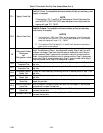
Cd30 In-Range Tolerance
The in-range tolerance will determine the band of temperatures around the set
point which will be designated as in-range. If the control temperature is in-range,
the in-range light will be illuminated. There are four possible values:
1=¦ 0.5_C(¦ 0.9_F)
2=¦ 1.0_C(¦ 1.8_F)
3=¦ 1.5_C(¦ 2.7_F)
4=¦ 2.0_C(¦ 3.6_F) -- Factory Default