


3-14T -309
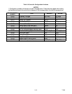
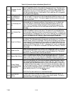
Table 3-5 Controller Function Codes (Sheet 1 of 3)
Code
No.
TITLE DESCRIPTION
Note: If the function is not applicable, the display will read “-- -- -- -- -- ”
Display Only Functions
Cd01
Suction Modulation
Valve Opening (%)
Displays the SMV percent open. The right display reads 100% when the valve is
fully open. The valve will usually be at 10% on start up of the unit except in very
high ambient temperatures.
Cd02 Not Applicable Not used
Cd03
Compressor Motor
Current
The current sensor measures current draw in lines L1 & L2 by all of the high
voltage components. It also measures current draw in compressor m otor leg T3.
The compressor leg T3 current is displayed.
Cd04
Cd05
Cd06
Line C urrent,
Phase A
Line C urrent,
Phase B
Line C urrent,
Phase C
The current sensor measures current on two legs. The third unmeasured leg is cal-
culated based on a current algorithm. The current measured is used for control
and diagnostic purposes. For control processing, the highest of the Phase A and B
current values is used for current limiting purposes. For diagnostic processing,
the current draws are used to monitor component energization.. Whenever a heat-
er or a motor is turned ON or OFF, the current draw increase/reduction for that
activity is measured. The current draw is then tested to determine if it falls within
the expected range of values for the component. Failure of this test will result in a
pre-trip failure or a control alarm indication.
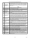
Cd07 Main Power Voltage The main supply voltage is displayed.
Cd08
Main Power Fre-
quency
The value of the main power frequency is displayed in Hertz. The frequency dis-
played will be halved if either fuse F1 or F2 is bad (alarm code AL21).
Cd09
Ambient Tempera-
ture
The ambient sensor reading is displayed.
Cd10
Compressor Suction
Te mperature
Compressor suction temperature sensor reading is displayed.
Cd11
Compressor Dis-
charge Temperature
Compressor discharge temperature sensor reading is displayed.
Cd12
Compressor Suction
Pressure
Compressor suction pressure transducer reading is displayed.
Cd13 Not Applicable Not used
Cd14
Compressor Dis-
charge Pressure
Compressor dischar ge pressure transducer reading is displayed.
Cd15 Unloader Valve The status of the valve is displayed (Open - Closed).
Cd16
Compressor Motor
Hour Meter
Records total hours of compressor run time. Total hours are recorded in incre-
ments of 10 hours (i.e., 3000 hours is displayed as 300).
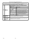
Cd17
Relative Humidity
(%)
Humidity sensor reading is displayed. This code displays the relative humidity, as
a percent value.
Cd18 Software Revision # The software revision number is displayed.
Cd19 Battery Check
This code checks the Controller/DataCORDER battery pack. While the test is
running, “btest” will flash on the right display, followed by the result. “PASS”
will be displayed for battery voltages greater than 7.0 volts. “FAIL” will be dis-
played for battery voltages between 4. 5 and 7.0 volts, and “-- -- -- -- --” will be
displayed for battery voltages less than 4.5 volts. After the result is displayed for
four seconds, “btest” will again be displayed, and the user may continue to scroll
through the various codes.
Cd20 Config/Model #
This code indicates the dash number of the model for which the Controller is con-
figured (i.e., if the unit is a 69NT40-531-100, the display will show “31100”).
Cd21 Economizer Valve The status of the valve is displayed (Open - Closed).