


6-17
T -309
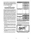
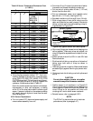
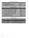
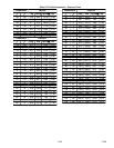
Table 6-2 Sensor Temperature/Resistance Chart
(+/--.002%)
Temperature
Resistance
_
__
_C _
__
_F
(Ohms)
C
F
AMBS,
CPSS,
DTS, RTS,
RRS, STS,
SRS
CPDS
-- 3 0 -- 2 2 177,000 1,770,000
-- 2 5 -- 1 3 130,400 1,340,000
-- 2 0 -- 4 97,070 970,700
-- 1 5 5 72,900 729,000
-- 1 0 14 55,330 553,000
-- 5 23 43,200 423,300
0 32 32,650 326,500
5 41 25,390 253,900
10 50 19, 900 199,000
15 59 15, 700 157,100
20 68 12, 490 124,900
25 77 10, 000 100,000
30 86 8,060 80,600
35 95 6,530 65,300
40 104 5,330 53,300
45 113 4,370 43,700
50 122 3,600 36,000
55 131 2,900 29,000
60 140 2,490 24,900
65 149 2,080 20,800
65 158 1,750 17,500
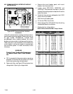
e. Using the plug connector marked “EC”, that is con-
nected to the back of the controller, locate the sensor
wires (RRS, RTS, SRS, STS, AMBS, DTS, CPDS
OR CPSS as required). Follow those wiresto the con-
nector and using the pins of the plug, measure the
resistance. Values are provided in Table 6-2.
Due to the variations and inaccuracies in ohmmeters,
thermometers or other test equipment, a reading
within 2% of the chart value would indicate a good
sensor. If a sensor is defective, the resistance reading
will usually be much higher or lower than the resis-
tance values given.
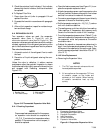
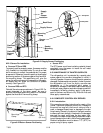
6.22.2 Sensor Replacement
a. Turn unit power OFF, disconnect power supply and
remove sensor assembly from unit.
b. Cut wire(s) 5 cm (2 inches) from shoulder of defec-
tive sensor and discard the defective probe only.
c. Cut one wire of existing cable 40 mm (1-1/2 inch)
shorter than the other wire.
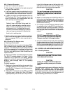
d. Cut one replacement sensor wire (opposite color)
back 40 mm (1-1/2 inch). (See Figure 6-19.)
e. Strip back insulation on all wiring 6.3 mm (1/4 inch).
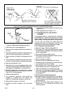
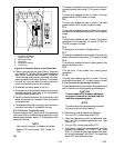
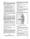
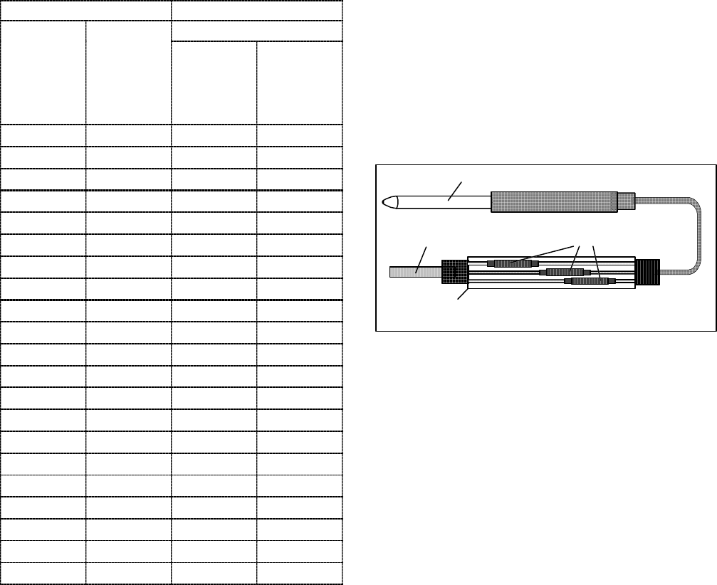
f. Slide a large piece of heat shrink tubing over the
cable, and place the two small pieces of heat shrink
tubing, one over each wire, before adding crimp fit-
tings as shown in Figure 6-20.
Sensor (Typical)
Cable
Heat Shrink
T ubing (3)
Large Heat Shrink
T ubing (1)
Figure 6-20 Typical Sensor and Cable Splice
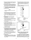
g. Slip crimp fittings over dressed wires (keeping wire
colors together). Make sure wires are pushed into
crimpfittingsas faraspossible andcrimpwith crimp-
ing tool.
h. Solder spliced wires with a 60% tin and 40% lead
Rosincore solder.
i. Slide heat shrink tubing over splice so that ends of
tubing cover both ends of crimp as shown in
Figure 6-20.
j. Heattubing to shrink oversplice.Make sureallseams
are sealed tightly against the wiring to prevent mois-
ture.
k. Slide large heat shrink tubing over both splices and
shrink.
CAUTION
Do not allow moisture to enter wire splice
area as this may affect the sensor resistance.
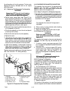
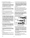
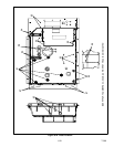
l. Position sensor in unit as shown in m.Figure 6-21
Slip crimp fittings over dressed wires (keeping wire
colors together). Make sure wires are pushed into
crimp fittings as far as possible and crimp with
crimping tool. and re--check sensor resistance.
n. Reinstall sensor, refer to paragraph 6.22.3.
NOTE
The P5 Pre-Trip test must be run to inactivate
probe alarms (refer to paragraph 4.7).