


6-4T-309
a. Remove all refrigerant using a refrigerant recovery
system.
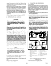
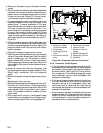
b. The recommended method to evacuate anddehydrate
the system is to connect evacuation hoses at the c om-
pressor suction, compressor economizer and liquid
line service valve (see Figure 6-5). Be sure the ser-
vice hoses are suited for evacuation purposes.
c. The area between the suction modulating valve and
evaporator expansion valve may not be open to the
access v alves. To ensure evacuation o f this area,
check that the suction modulating valve is more than
10% open at controller function code Cd01. If re-
quired, the suction modulating valve may be opened
by use of the controller function code Cd41 valve
override control. If power is not available to open the
valve, the area may be evacuated by connecting an
additional hose at the low side access valve (item 11,
Figure 2-2).
d. Test the evacuation setup for leaks by backseating the
unit service valves and drawing a deep vacuum with
thevacuum pump andgaugevalves open. Shut offthe
pump and check to see if the vacuum holds. Repair
leaks if necessary.
e. Midseat the refrigerant system service valves.
f. Openthe vacuumpump and electronic vacuum gauge
valves, if they are not already open. Start the vacuum
pump. Evacuate unit until the electronic vacuum
gauge indicates 2000 microns. Close the electronic
vacuum gauge and vacuum pump valves. Shut offthe
vacuum pump. Wait a few minutes to be sure the vac-
uum holds.
g. Break the vacuum with clean dry refrigerant 134a
gas. Raise system pressure to approximately 0.2 kg/
cm@ (2 psig), monitoring it with the compound
gauge.
h. Remove refrigerant using a refrigerant recovery sys-
tem.
i. Repeat steps f.and g. one time.
j. Remove the copper tubing and change thefilter-drier.
Evacuate unit to 500 microns. Close the electronic
vacuum gauge and vacuum pump valves. Shut offthe
vacuum pump. Wait five minutes to see i f vacuum
holds. This procedure checks for residual moisture
and/or leaks.
k. With a vacuum still in the unit, the refrigerant charge
may be drawn into the system from a refrigerant con-
tainer on weight scales. Continue to paragraph 6.7
6
4
5
7
DS
10
1
2
3
8
9
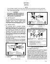
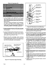
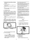
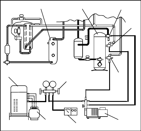
1. Receiver or Water
Cooled Condenser
2. Compressor
3. Discharge Service
Valve
4. Economizer Service
Valve
5. Suction Service Valve
6. Vacuum Pump
7. Electronic Vacuum
Gauge
8. Manifold Gauge Set
9. Refrigerant Cylinder
10. Reclaimer
Figure 6-6. Compressor Service Connections
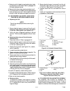
6.6.4 Procedure - Partial System
a. If the refrigerant charge has been removed from the
compressor for service, evacuate only the compressor
by connecting the evacuation set--up at the compres-
sor service valves. (See Figure 6-6.) Follow evacua-
tion procedures of the preceding paragraph except
leave compressor service v alves frontseated u ntil
evacuation is completed.
b. If refrigerant charge has been removed from the low
side only, evacuate t he low side by connecting the
evacuation set--up at the compressor suction and
economizer service valves and the liquid service
valve except leave the service valves frontseated until
evacuation is completed.
c. Once evacuation has been completed and the pump
has been isolated, fully backseat the service valves to
isolate the service connections and then continue
with checking and, if required, adding refrigerant in
accordance with normal procedures