


T -309 4-4
1. At every power up.
2. At the end of every defrost.
3. After every diagnostic check that does not fall out-
side of the limits as outlined above.
d. Probe C heck
A defrost cycle probe check is acco mplished by
energizing just the evaporator motors for eight minutes
at the end of the normal defrost. At the end of the eight
minute period t he probes will be compared to a set of
predetermined limits. The defrost indicator will remain
on throughout this period.
Any probe(s) determined to be outside the limits will
cause the appropriate alarm code(s) to be displayed to
identify w hich probe(s) needs to be replaced. The P5
Pre-Trip test must be run to inactivate alarms.
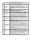
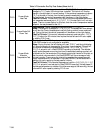
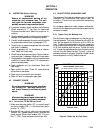
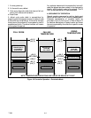
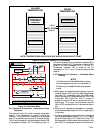
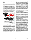
4.9 SEQUENCE OF OPERATION
General operation sequences for cooling, heating and
defrost are provided in the following subparagraphs.
Schematic representation of controller action are
provided in
Figure 4-2 and Figure 4-3. Refer to Section 3
for detailed descriptions of special events and timers
that are incorporated by the controller in specific modes
of operation.
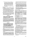
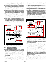
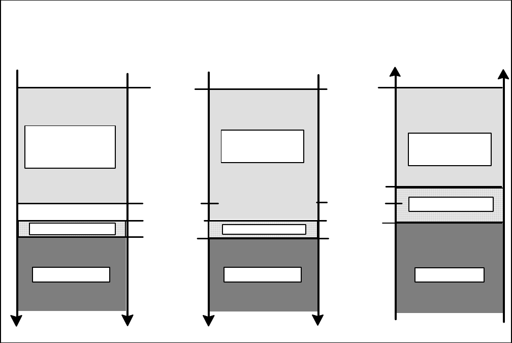
SET POINT
PULL DOWN
RISING
TEMPERATURE
-- 0 . 5 _C
(0.9_F)
--0.20_C
+.20_C
HEATING
HEATING
AIR CIRCULATION
+2.5_C
(4.5_F)
UNLOADED OPERATION
MODULATED
COOLING
UNLOADED
AIR CIRCULATION
SET POINT
+.20_C
HEATING
+2.5_C
(4.5_F)
FALLING
TEMPERATURE
MODULATED
COOLING
UNLOADED
-- 0 . 5 _C
(0.9_F)
AIR CIRCULATION
NOTE: TEMPERATURES INDICATIONS ARE ABOVE OR BELOW SET POINT
START UNLOADED,
TRANSITION TO
ECONOMIZED
OPERATION
--0.20_C
Figure 4-2 Controller Operation -- Perishable Mode