


T -309 4-2
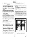
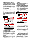
4.4 C ONNECT REMOTE MONITORING
RECEPTACLE
If remote monitoring is required, connect remote
monitor plug at unit receptacle. (See item 9,Figure 2-5.)
When the remote m onitor plug is connected to the
remote monitoring receptacle, the following remote
circuits are energized:
CIRCUIT FUNCTION
Sockets B to A Energizes remote cool light
Sockets C to A Energizes remote defrost light
Sockets D to A Energizes remote in-range light
4.5 STARTING AND STOPPING INSTRUCTIONS
WARNING
Make sur e that the unit circuit breaker(s)
(CB-1 & CB-2) and the START-STOP
switch(ST ) are in the“O”(OFF) positionbe-
fore connecting to any electrical power
source.
4.5.1 Starting the Unit
1. With powerproperly applied, the fresh air damper set
and (if required) the water cooled condenser con-
nected, (refer to paragraphs 4.2 & 4.3) place the
START-STOP switch to “I” (ON).
NOTE
Within the first 30 seconds the electronic phase
detection system will check for proper com-
pressor rotation. If rotation is not correct, the
compressor will be stopped and restarted in the
opposite direction. Ifthe compressor is produc-
ing unusually loud and continuous noise after
the first 30 seconds of operation, stop the unit
and investigate.
2. Continue with Start Up Inspection, paragraph 4.6.
4.5.2 Stopping the Unit
To stop the unit, place the S TART-STOP switch in
position “0” (OFF).
4.6 START--UP INSPECTION
4.6.1 Physical Inspection
a. Check rotation of condenser and evaporator fans.
b. Check compressor oil level. (Refer to paragraph 6.9.)
4.6.2 Check Controller Function Codes
Check and, if required, reset controller Function Codes
(Cd27 through Cd39) in accordance with desired
operating parameters. Refer to paragraph 3.2.2.
DataCORDER
a. Check and, if required, set the DataCORDER Con-
figuration in accordance with desired recording pa-
rameter. Refer to paragraph 3.6.3.
b. Enter a “Trip Start”. To enter a “trip Start”, do the
following:
1. Depress the ALT MODE key and scroll to Code
dC30.
2. Depress and hold the ENTER key for five seconds.
3. The “Trip Start” event will be entered in the Data-
CORDER.
4.6.3 Complete Inspection
Allow unit to run for 5 minutes to stabilize conditions
and perform a pre--trip diagnosis in accordance with the
following paragraph.
4.7 PRE-TRIP DIAGNOSIS
CAUTION
Pre-trip inspection should not be performed
with critical temperature cargoes in the con-
tainer.
CAUTION
When Pre-Trip key is pre ssed, economy, de-
humidification and bulb mode will be deac-
tivated. At the completion of Pre-Trip activi-
ty, economy, dehumidification and bulb
mode must be reactivated.
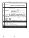
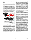
Pre-Trip diagnosis provides automatic testing of the
unit components using internal measurements and
comparison logic. The program will provide a “PASS”
or “FAIL” display to indicate test results.
The testing begins with access to a pre-trip selection
menu. The user may have the option of selecting one of
two automatic tests. These tests will automatically
perform a series of individual pre--trip tests. The user
may also scroll down to select any of the individual
tests. When only t he short sequenceis configured it will
appear as “AUtO” in the display, otherwise “AUtO1”
will indicate the short sequence and “AUtO2” will
indicate the long sequence. The test short sequence will
run tests P0 through P6. The long test sequence will run
tests P0 through P10.
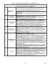
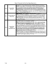
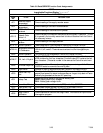
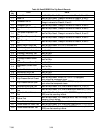
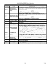
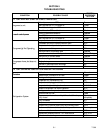
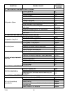
A detailed description of the pre-trip test codes is listed
in Table 3-7, page 3-21. If no selection is made, the
pre-trip menu selection process will terminate
automatically. However, dehumidification and bulb
mode must be reactivated manually if required.
Scrolling down to the “rSLts” code and pressing
ENTER will allow the user to scroll through the results
ofthe last pre--trip testing run. If no pre--testing hasbeen
run (or an individual t est has not been run) since the unit
was powered up “--------” will be displayed.
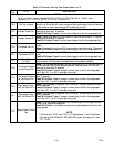
To start a pre--t rip test, do the following:
NOTE
1. Priorto startingtests, verifythatunitvoltage
(Function Code Cd 07) is within tolerance
and unit amperage draw (Function Codes
Cd04, Cd05, Cd06) are withi n expected
limits. Otherwise, tests may fail incorrectly.
2. All alarms must be rectified and cleared
before starting tests.