


T -309
2-1
SECTION 2
DESCRIPTION
2.1 GENERAL DESCRIPTION
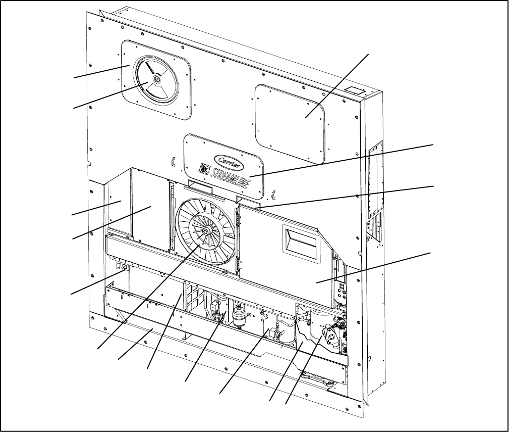
2.1.1 Refrigeration Unit -- Front Section
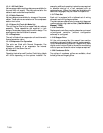
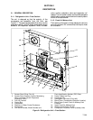
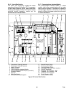
The unit is designed so that the majority of the
components are accessible from the front, see
Figure 2-1. The upper access panels allow entry into the
evaporator section, and the center access panel allows
access to the evaporator expansion valve, unloader
valve, suction modulation valve and evaporator coil
heaters. The unitmodelnumber, serial number andparts
identification number can be found on the serial plate to
the left of the economizer.
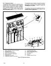
2.1.2 Fresh Air Makeup V ent
The function of t he upper or lower makeup air vent is to
provide ventilation for commodities that require fresh
air circulation.
1
2
3
8
4
11
5
12
14
9
15
13
10
6
7
16
1. Access Panel (Evap. Fan #1)
2. Access Panel (Heaters, Suction Modulating
Valve, Unloader Valve & Evaporator
Expansion Valve)
3. Fork Lift Pockets
4. Control Box
5. Compressor
6. Receiver or Water Cooled Condenser
7. Economizer
8. Unit Serial Number, Model Number and
Parts Identification Number (PID) Plate
9. Power Cables and Plug
10. Condenser Fan
11. Interrogator Connector (Front left)
12. Blank Cover (Temperature Recorder Location)
13. Blank Cover (Lower Fresh Air Makeup Vent
Location)
14. Upper Fresh Air Makeup Vent
15. Access Panel (Evap. Fan #2)
16. Compressor Protection Panel (cutaway view)
Figure 2-1 Refrigeration Unit -- Front Section