


6-1
T -309
SECTION 6
SERVICE
NOTE
Toavoid damage to theearth’s ozone layer, use a refrigerant recovery system whenever removingrefrigerant.
When working with refrigerants you must comply with all local government environmental laws. In the
U.S.A., refer to EPA section 608.
WARNING
Never use air for leak testing. It has been de-
termined that pressurized, mixtures of re-
frigerant and air can undergo combustion
when exposed to an ignition source.
6.1 SECTION LAYOUT
Service procedures are provided herein beginning with
refrigeration system service, then refrigeration system
component service, electrical system service,
temperature recorder service and general service. Refer
to the Table Of Contents to locate specific t opics.
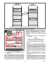
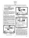
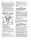
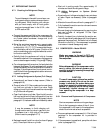
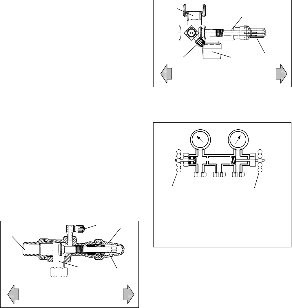
6.2 SERVICE VALVES
The compressor suction, compressor discharge,
compressor economizer, oil return and the liquid line
service valves (see Figure 6-1) are provided with a
double seat and an access valve which enable servicing
of the compressor and refrigerant lines. Turning the
valve stem clockwise (all the way forward) will
frontseat the valve to close off the line connection and
open a p ath to t he access valve. Tu rning the s tem
counterclockwise (all the way out) will backseat the
valve to open the line connection and close off the path
to the access valve.
With the valve stem midway between frontseat and
backseat, both of the service valve connections are open
to the access valve path.
For example, the valve stem is first fully backseated
when connecting a manifold gaugeto measurepressure.
Then, the valve is opened 1/4 to 1/2 turn to measure the
pressure.
VALVE
FRONTSEATED
(Clockwise)
VALVE
BACKSEATED
(Counterclockwise)
5
1
2
3
4
1. Line Connection
2. Access Valve
3. Stem Cap
4. Valve stem
5. Compressor Or Filter
Drier Inlet Connection
Figure 6-1 Service Valve
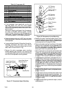
VALVE
FRONTSEATED
(Clockwise)
VALVE
BACKSEATED
(Counterclockwise)
5
1
2
3
4
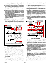
1. Line Connection
2. Access Valve
3. Stem Cap
4. Valve stem
5. Compressor Inlet
Connection
Figure 6-2 Suction Service Valve
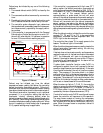
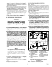
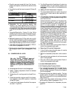
OPENED (Backseated )
HAND VA LVE
CLOSED (Frontseated)
HAND VA LVE
SUCTION
PRESSURE
GAUGE
DISCHARGE
PRESSURE
GAUGE
A
BC
A. CONNECTION TO LOW SIDE OF SYSTEM
B. CONNECTION TO EITHER:
REFRIGERANT CYLINDER OR
OIL CONTAINER
C. CONNECTION TO HIGH SIDE OF SYSTEM
Figure 6-3 Manifold Gauge Set
6.3. MANIFOLD GAUGE SET
The manifold gauge set (see Figure 6-3) is used to
determine system operating pressure, add refrigerant
charge, and to equalize or evacuate the system.
When the suction pressure hand valve is frontseated
(turned all the way in), thesuction (low) pressure can be
checked. When the discharge pressure hand valve is
frontseated, the discharge (high) pressure can be
checked. When both valves are open (turned
counter-clockwise all the way out), high pressure vapor
will flow into the low side. When the suction pressure
valve is open and the discharge pressure valve shut, the