


6-11
T -309
c. Determine which heater(s) need replacing by check-
ing resistance on each heater. Refer to paragraph 2.3
for heater resistance values
d. Remove hold-down clamp securing heaters to coil.
e. Lift the bent end of the heater (with the opposite end
down and away from coil). Move heater to the side
enough to clear the heater end support and remove.
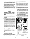
6.16 ECONOMIZER, UNLOADER, LIQUID INJEC-
TION AND OIL RETURN SOLENOID VALVE
a. Replacing the Coil
NOTE
The coil may be replaced without removing the
refrigerant.
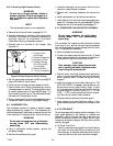
1 B e sure electrical power is removed from the unit.
Disconnect leads. Remove top screw and washer.
Lift off coil. (See Figure 6-14 or Figure 6-15)
2 Verify coil type, voltage and frequency of old and
new coil. This information appears on the coil hous-
ing.
b.
Replacing Valve Internal Parts (Unloader
Solenoid Only)
1 Pump down the unit. Refer to paragraph 6.4.
2 B e sure electrical power is removed from the unit.
Disconnect leads. Remove top screw and washer.
Lift off coil. (See Figure 6-14)
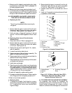
3 R emove the top screw (see Figure 6-14), washer ,
and coil assembly.
4 Loosen the enclosing tube locknut.
5 R emove enclosing tube and locknut assembly. The
gasket is inside the enclosing tube.
6 R emove seat disc from inside of body and check for
obstructions and foreign material.
7 P lacethe seat discinto the valvebodywith thesmall-
er diameter end facing up.
8 Install stem and plunger.
9 Place the enclosing tube locknut over the enclosing
tube. Install spacer over enclosing tube making sure
it is seated properly in the enclosing tube locknut.
Tighten enclosing tube locknut to a torque value of
2.78 mkg (20 ft-lb). Do not overtighten.
10 Install coil assembly, washer and top screw.
11 Evacuateand dehydrate thesystem. (Referto section
6.6.) Charge unit with refrigerant per section 6.7.
12 Start unit and check operation.
c.
Replacing Valve
1 To replace the unloader, liquid injection or econo-
mizervalve,pump downthe unit. Refer to paragraph
6.4. To replace the oil return valve, remove the re-
frigerant charge.
2 B e sure electrical power is removed from the unit.
Disconnect leads. Remove top screw and washer.
Lift off coil. (See Figure 6-14 or Figure 6-15)
3 Unbraze valve from unit and braze new valve in
place
4 Install coil. Evacuate low side and place unit back
in operation. Check charge.
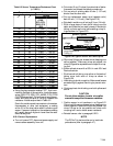
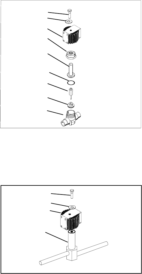
1
9
8
7
6
5
4
3
2
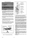
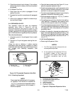
1. Top Screw
2. Wa sher
3. Coil
4. Locknut
5. Enclosing Tube
6. Gasket
7. Stem and Plunger
8. Seat Disc
9. Body
Figure 6-14. Unloader Solenoid Valve
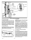
1
2
3
4
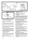
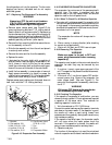
1. Slotted Screw
2. Wa sher
3. Coil
4. Enclosing T ube and
Body
Figure 6-15. Oil Return Solenoid Valve (ORV),
Economizer Solenoid Valve (ESV), Liquid
Injection Solenoid Valve (LIV)
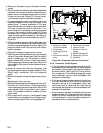
6.17 EVAPORATOR FAN AND MOTOR ASSEMBLY
The evaporator fans circulate air throughout the
container by pulling air in the top of the unit. The air is
forced through the evaporator coil where it is either
heated or cooled and then discharged out the bottom of