


6-2T-309
system can be charged. Oil can also be added to the
system.
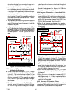
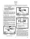
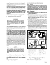
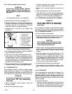
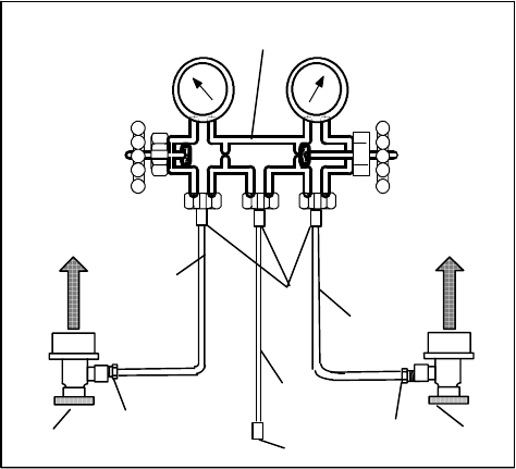
A R-134a manifold gauge/hose set with self-sealing
hoses (see Figure 6-4) is required for service of the
models covered within this manual. The manifold
gauge/hose set is available from Carrier Transicold.
(Carrier Transicold P/N 07-00294-00, which includes
items1 through 6, Figure 6-4.) Toperformserviceusing
the manifold gage/hose set, do the following:
a. Preparing Manifold Gauge/Hose Set For Use
1. If themanifold gauge/hoseset is new or wasexposed
to the atmosphere it will need to be evacuated to
remove contaminants and air as follows:
2. Back seat (turn counterclockwise )both field service
couplings (see Figure 6-4) and midseat both hand
valves.
3. Connect the yellow hose to a vacuum pump and re-
frigerant 134a cylinder.
OPENED
(Backseated )
HAND VALVE
CLOSED
(Frontseated)
HAND V A LV E
SUCTION
PRESSURE
GAUGE
DISCHARGE
PRESSURE
GAUGE
To Low Side
Access Valve
To High Side
Access Valve
Red Knob
Blue Knob
1
4
3
YELLOW
2
4
5
6
3
RED
3
BLUE
2
1. Manifold Gauge Set
2. Hose Fitting (0.5-16 Acme)
3. Refrigeration and/or Evacuation Hose
. (SAE J2196/R-134a)
4. Hose Fitting w/O-ring (M14 x 1.5)
5. High Side Field Service Coupling
6. Low Side Field Service Coupling
Figure 6-4 R-134a Manifold Gauge/Hose Set
7. Evacuate to 10 inches of vacuum and then charge
with R-134a to a slightly positive pressure of 0.1 kg/
cm@ (1.0 psig).
8. Front seat both manifold gauge set valves and dis-
connect from cylinder. The gauge set is now ready
for use.
b. Connecting Manifold Gauge/Hose Set
To connect the manifold gauge/hose set for reading
pressures, do the following:
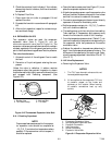
1. Remove service valve stem cap and check to make
sure it is backseated. Remove access valve cap.
(See
Figure 6-1)
2. Connect the field service coupling (see Figure 6-4)
to the access valve.
3. Turn the field service coupling knob clockwise,
which will open the system to the gauge set.
4. To read system pressures: slightly midseat the ser-
vice valve.
5. Repeat the procedure to connect the other side of the
gauge set.
CAUTION
To prevent trapping liquid refrigerant in the
manifold gauge set b e sure set is brought to
suction pressure b efore di sconn ecting.
c. Removing the Manifold Gauge Set
1. While the compressor i s still ON, backseat the high
side service valve.
2. Midseat both hand valves on the manifold gauge set
and allow the pressure in the manifold gauge set to
bedrawn downto low side pressure. This returns any
liquid thatmay bein the highside hoseto the system.
3. Backseat the low side service valve. Backseat both
field service couplings and frontseat both manifold
set valves. Remove the c ouplings from the access
valves.
4. Install both service valve stem caps and service port
caps (finger-tight only).
6.4 PUMPING THE UNIT DOWN
To service the filter-drier, economizer, expansion
valves, moisture-liquid indicator, suction modulation
valve, economizer solenoid valve, unloader solenoid
valve or evaporator coil, pump the refrigerant into the
high side as follows:
CAUTION
The scroll compressor achieves low suction
pressure very quickly. Do not operate the
compr essor in a deep vacuum, internal dam-
age will result.
a. Attach manifold gauge set to the compressor suction
and discharge service valves. Refer to paragraph 6.3.
b. Start the unit and run in the frozen mode (controller
set below --10°C)for10to15minutes.
c. Check function code Cd21 (refer to paragraph 3.2.2).
The economizer solenoid valve should be open. If
not, continue to run until the valve opens.
d. Frontseat the oil return service valve then, frontseat
theliquid line servicevalve.Placestart-stop switchin
the OFF position when the suction reaches a positive
pressure of 0.1 kg/cm@ (1.0 psig).
e. Frontseat the economizer service valve and then
frontseat the suction and discharge service valves.
The refrigerant will be trapped between thecompres-
sor suction service valve and the liquid line valve.
f. Before opening up any part of the system, a slight
positive pressure should be i ndicated on the pressure