


6-18T -309
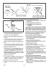
SRS probe
STS probe
Supply
Air
Stream
Mounting
Clamp
Supply Sensor
Sensor
Wires
Back Panel
2.5”Drip Loop
T.I.R. Bolts
Gasketed
Support
Plate
Gasket
Mounting
Plate
Insulation
Gasketed
Cover
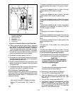
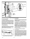
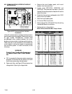
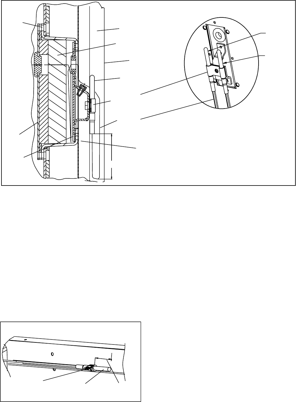
Figure 6-21 Supply Sensor Positioning
6.22.3 Sensor Re--Installation
a. Sensors STS and SRS
Toproperly position a supply sensor, the sensor must be
fully inserted into the probe holder. Do not allow heat
shrink covering to contact the probe holder. F or proper
placement of the sensor, be sure to position the enlarged
positioning section of the sensor against the the side of
the mounting clamp. This positioning will give the
sensor the optimum amount of exposure to the supply
air stream, and will allow the Controller to operate
correctly. See Figure 6-21.
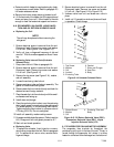
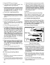
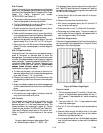
b Sensors RRS and RTS
Reinstall the return sensor as shown in Figure 6-22. For
proper placement of the return sensor , be sure to
position the enlarged positioning section of the sensor
against the the side of the mounting clamp.
Return Sensor
Mounting
Clamp
1.50 in.
(38.1cm)
Figure 6-22 Return Sensor Positioning
c Sensor DTS
The DTS sensor must have insulating material placed
completely over the sensor to insure the coil metal
temperature is sensed.
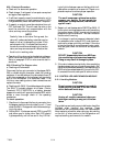
6.23 MAINTENANCE OF PAINTED SURFACES
The refrigeration unit is protected by a special paint
system against the corrosive atmosphere in which it
normallyoperates. However,should t he paint system be
damaged, the base metal can corrode. In order to protect
the refrigeration unit from the highly corrosive sea
atmosphere, or if the protective paint system is
scratched or damaged, clean area to bare metal using a
wire brush, emery paper or equivalent cleaning method.
Immediately following cleaning, apply 2--part epoxy
paint to the area. and allow to dry. After the first coat
dries, apply a second coat.
6.24 COMPOSITE CONTROL BOX REPAIRS
6.24.1 Introduction
This procedure provides i nstructions for repair of the
Carrier Transicold composite control box. Damage to
the control box may be in the form of a chip or hole, a
crack, a damaged thread insert or damage to the door
hinge inserts. Generally, the object of the repair must be
to ensure sufficient strength is restored to the damaged
area and the repair must keep the box water tight.
Information on repair kits and repairprocedures foreach
type of damage is provided in the following paragraphs.
Ambient temperature must be above 7°C(45°F) for
proper curing of epoxy repairs.