


T -309
2-9
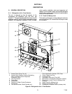
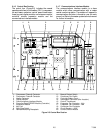
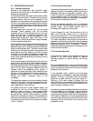
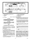
2.5 R EFRIGERATION CIRCUIT
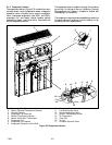
2.5.1 Standard Operation
Starting at the compressor, (see Figure 2-6, upper
schematic) the suction gas is compressed to a higher
pressure and temperature.
In the standard mode, both the economizer andunloader
solenoid valves are closed. The gas flows through the
discharge service valve into the oil separator. In the
separator, oil is removed from the refrigerant and stored
forreturnto the compressorwhen the oil return solenoid
valveis openedby thecontroller. The oil returnsolenoid
valveis a normally openvalvewhich allowsreturn ofoil
during t he off cycle.
The refrigerant gas continues into the air-cooled
condenser. When operating with the air-cooled
condenser active, air flowing across the coil fins and
tubes cools the gas to saturation temperature. By
removing latent heat, the gas condenses to a high
pressure/high temperature liquid and flows to the
receiver which stores the a dditional charge necessary
for low temperature operation.
When operating with the water cooled condenser active
(see Figure 2-6, lower schematic), the refrigerant gas
passes through the air cooled condenser and enters the
water cooled condenser shell. The water flowing inside
the tubing cools the gas to saturation temperature in the
same manner as the air passing over the air cooled
condenser. The refrigerant condenses on the outside of
the t ubes and exits as a high t emperature liquid. The
water cooled condenser also acts as a receiver, storing
excess refrigerant.
The liquid refrigerant continues through the liquid line
service valve, the filter-drier (which keeps refrigerant
clean and dry) and the economizer (which is not active
during standard operation) to the evaporator expansion
valve. As the liquid refrigerant passes through the
variable orifice of the expansion valve, some of it
vaporizes into a gas (flash gas). Heat is absorbed from
the return air by the balance of the liquid, causing it to
vaporize in the evaporator coil. The vapor then flows
through the suction modulation valve to the
compressor.
The evaporator expansion valve is activated by the bulb
strapped to the suction line near the evaporator outlet.
The valve maintains a constant superheat at the coil
outlet regardless of load conditions.
On systems fitted with a water pressure switch, the
condenser fan will be off when there is sufficient
pressure to open the switch. If water pressure drops
below the switch cut out setting, the condenser fan will
be automatically started. When operating a system
fitted with a condenser fan switch, the condenser fan
will be off when the switch is placed in the “ O”position.
The condenser fan will be on when the switch is placed
in the “I” position.
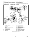
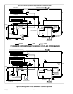
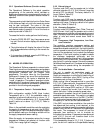
2.5.2 Economized Operation
In the economized mode thefrozen rangeand pull down
capacityof the unit isincreased by subcooling the liquid
refrigerant entering the evaporator expansion valve.
Overall efficiency is increased because the gas leaving
the economizer enters the compressor at a higher
pressure, therefore requiring less ener gy to compress it
to the required condensing conditions.
During economized operation, flow of refrigerant
through the main refrigerant system is identical to the
standard mode. (The unloader solenoid valve is
de--energized [closed] by the controller.)
Liquid refrigerant for use in the economizer circuit is
taken from the main liquid line as it leaves the
filter--drier (see Figure 2-7). The flowis activated when
the controller energizes the economizer solenoid valve.
The liquid refrigerant flows through the economizer
expansion valve and the economizer internal passages
absorbing heat from the liquid refrigerant flowing to the
evaporator expansion valve. The resultant “medium”
temperature/pressure gas enters the compressor at the
economizer service valve.
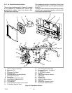
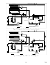
2.5.3 Unloaded Operation
The system will operate in the unloaded mode during
periods of low load, during periods of required
discharge pressure or current limiting, and during
start--up.
During unloaded operation, flow of refrigerant through
the main refrigerant system is identical to the standard
mode. (The economizer solenoid valve is de--energized
[closed] by the controller.)
In the unloaded mode, a portion of the mid--stage
compressed gas is bypassed to decrease compressor
capacity. The flow i s activated when t he controller
opens the unloader solenoid valve (see Figure 2-7.
Opening of the valve creates a bypass from the
economizerservicevalve throughthe unloadersolenoid
valve and into the suction line on the outlet side of the
suction pressure modulation valve.
As loadon thesystem decreases,the suctionmodulating
valve decreases flow of refrigerant to the compressor.
This action balances the compressor capacity with the
load and prevents operation with low coil temperatures.
In this mode of operation, the liquid injection solenoid
valve will open as required to provide sufficient liquid
refrigerant flow into the suction line for cooling of the
compressor motor.