


3-20T -309
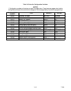
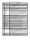
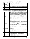
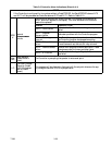
Table 3-6 Controller Alarm Indications (Sheet 4 of 4)
NOTE
If the C ontroller is configured for four probes without a DataCORDER, the DataCORDER alarms AL70
and AL71 will be processed as Controller alarms AL70 and AL71. Refer to Table 3-10.
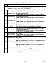
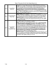
The Controller performs self-check routines. if an internal failure occurs, an
“ERR” alarm will appear on the display. This is an indication the Controller
needs to be replaced.
ERROR DESCRIPTION
ERR 0 -- RAM failure
Indicates that the Controller working memory has
failed.
ERR
Internal
M
i
c
r
o
p
r
o
c
e
s
s
o
r
EER 1 -- Program
Memory failure
Indicates a problem with the Controller program.
E
R
R
#
M
i
croprocessor
Failure
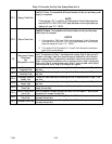
EER 2 -- Watchdog
time--out
The C ontroller program has entered a mode whereby
the C ontroller program has stopped executing.
EER 3 -- On board timer
failure
The on board timers are no longer operational.
Timed items such as; defrost, etc. may not work.
EER 4 -- Internal counter
failure
Internal multi-purpose counters have failed. These
counters are used for timers and other items.
EER 5 -- A-D failure
The C ontroller’s Analog to Digital (A-D) converter
has failed.
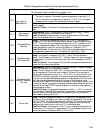
Entr
StPt
Enter Setpoint
(Press Arrow &
Enter)
The Controller is prompting t he operator to enter a set point.
LO
Low Main Voltage
(Function Codes
Cd27--38 disabled
and NO alarm
stored.)
This message will be alternately displayed with the set point whenever the sup-
ply voltage is less than 75% of its proper value.