


T -309
2-5
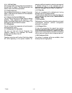
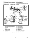
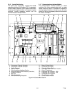
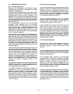
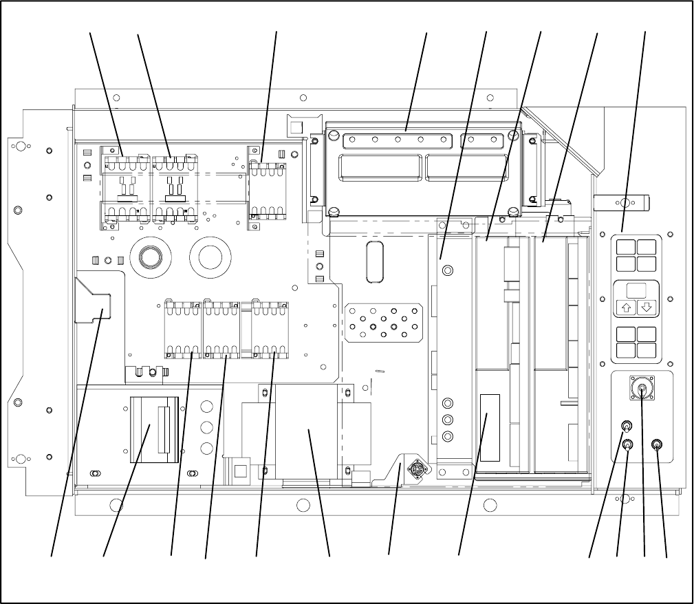
2.1.6 Control Box Section
The control box (Figure 2-5) includes the manual
operation switches; circuit breaker (CB-1); compressor,
fan and heater contactors; control power transformer;
fuses; key pad; display module; current sensor module;
controller module expansion module and the
communications interface module.
2.1.7 Communications Interface Module
The communications interface module i s a slave
module which allow communication with a master
central monitoring station. The module will respond to
communication and return information over the main
power line. Refer to the master system technical manual
for further information.
1920 151718
12 3 4 5 6 7
10 911
14
8
121316
1. Compressor Phase A Contactor
2. Compressor Phase B Contactor
3. Heater Contactor
4. Display Module
5. Communications Interface Module
6. Controller/DataCORDER Module (Controller)
7. Expansion Module
8. Key Pad
9. Start-Stop Switch
10. Rem ote Monitoring Receptacle
11. Manual Defrost Switch
12. Condenser Fan Switch
13. Controller Battery Pack
14. Interrogator Connector (Box Location)
15. Control Transformer
16. E vaporator Fan Contactor - High
17. E vaporator Fan Contactor - Low
18. Condenser Fan Contactor
19. Circuit Breaker -- 460V
20. Current Sensor Module
Figure 2-5 Control Box Section