


6-10T -309
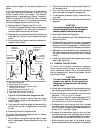
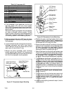
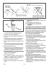
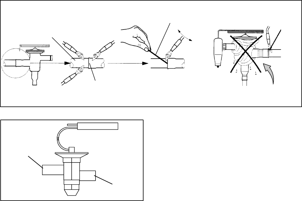
Copper Tube
(Apply heat for
10-15 seconds)
Bi-metallic T ube Connection
(Apply heat for 2-5 seconds)
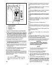
Use of a wet cloth is not neces-
sary due to rapid heat dissipation
of the bi--metallic connections
Braze Rod
(’Sil-Phos” = 5.5% Silver, 6% Phosphorus)
Figure 6-12 Hermetic Thermostatic Expansion Valve Brazing Procedure
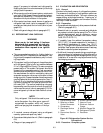
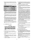
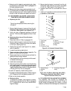
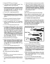
INLET
OUTLET
Figure 6-13 Economizer Expansion Valve
1. Pump down the unit per paragraph 6.4.
2. Removecushionclamps located on the inlet andout-
let lines.
3. Unbrazethe equalizer connection (if applicable), the
outlet connection and then the inlet connection.
4. Remove insulation (Presstite) from expansion valve
bulb.
5. Unstrap thebulb, located belowthe centerof the suc-
tion line (4 o’clock position), and remove the valve.
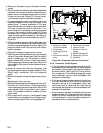
b. Installing the Expansion Valve
1. C l ean the suction line with sandpaper before instal-
ling bulb to ensure proper heat transfer. Apply t her-
mal grease to the indentation in the suction line.
2. Strap the thermal bulb to the suction line, making
sure bulb is placed firmly into the suction line. See
Figure 6-10 for bulb placement.
3. Insulate the thermal bulb.
4. The economizer expansion valves should be
wrapped in a soaked cloth for brazing. See
Figure 6-12. Braze inlet connection t o inlet line
5. Braze outlet connection to outlet line.
6. Reinstall the cushion clamps on inlet and outlet
lines.
7. If applicable, braze the equalizer connection to the
equalizer line.
8. Check superheat (refer to step 6.14.1).
6.15 EVAPORATOR COIL AND HEATER
ASSEMBLY
The evaporator section, including the coil, should be
cleaned regularly. The preferred cleaning fluid is fresh
wateror steam. Anotherrecommendedcleaneris Oakite
202 or similar, following manufacturer’s instructions.
The two drain pan hoses are routed behind the
condenser fan m otor and compressor. The drain pan
line(s) must be open to ensure adequate drainage.
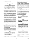
6.15.1 Evaporator Coil Replacement
a. Pump unit down. (Refer to paragraph 6.4.)
b. With power OF F and power plug removed, remove
the screws securing the panel covering the evaporator
section (upper panel).
c. Disconnect the defrost heater wiring.
d. Disconnect the defrost temperature sensor (see Fig-
ure Figure 2-2 from the coil. .
e. Remove middle coil support.
f. Remove the mounting hardware from the coil.
g. Unsolder the two coil connections, one at the distrib-
utor and the other at the coil header.
h. After defective coil is removed from unit, remove
defrost heaters and install on replacement coil.
i. Install coil assembly by reversing above steps.
j. Leak check connections per paragraph 6.5. Evacuate
the unit per paragraph 6.6 and add refrigerant charge
per paragraph 6.7.
6.15.2 Evaporator Heater Replacement
a.Beforeservicing unit, makesurethe unit circuitbreak-
ers (CB-1 & CB-2) and the start-stop switch (ST) are
in theOFF position, and thatt he powerplugandcable
are disconnected.
b. Remove the lower access panel (Figure 2-1) by
removing the T.I.R. locking device lockwire and
mounting screws.