


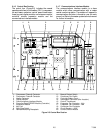
2-4T-309
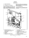
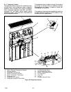
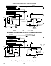
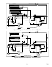
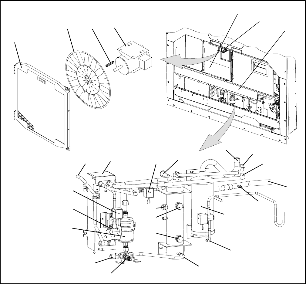
2.1.5 Air Cooled Condenser Section
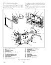
The air cooled condenser section (Figure 2-4) consists
of the condenser fan, condenser coil, receiver, sight
glass/moisture indicator, liquid line service valve,
filter-drier and fusible plug.
The condenser fan pulls air in the bottom of the coil and
it is discharged horizontally out through the condenser
fan grille.
This section also contains the economizer, economizer
solenoid valve, economizer expansion valve and the
liquid injection solenoid valve.
5
6
7
17
1
2
4
3
8
11
9
12
15
14
16
27
18
19
20
21
22
23
24
25
26
10
13
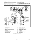
1. Grille and Venturi Assembly
2. Condenser Fan
3. Key
4. Condenser Fan Motor
5. Condenser Coil
6. Condenser Motor Mounting Bracket
7. Condenser Coil Cover
8. Economizer
9. To Evaporator Expansion Valv e
10. Liquid Injection Solenoid Valv e
11. From Condenser
12. To Condenser
13. To Compressor Economizer Connection
14. To Unloader Solenoid Valv e
15. From Compressor Discharge
16. Discharge Pressure Transducer
17. Oil Separator
18. To Oil Return Solenoid
19. Receiver
20. Sight Glass/Moisture Indicator
21. Sight Glass
22. Fusible Plug
23. Access Valve
24. Liquid Line Service Valve
25. Filter-Drier
26. Economizer Expansion Valve
27. Economizer Solenoid Valve
Figure 2-4 Condenser Section