


6-9
T -309
2. C heck the moisture-liquid indicator if the indicator
showsa high level ofm oisture, thefilter-driershould
be replaced.
b. To Replace Filter-Drier
1. Pump down the unit (refer to paragraph 6.4 and
replace filter-drier.
2. Evacuate the low side in accordance with paragraph
6.6.
3. After uniti s in operation, inspect for moisture in sys-
tem and check charge.
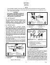
6.14 EXPANSION VALVES
Two expansion valves are used, the evaporator
expansion valve (item 9, Figure 2-2), and the
economizer expansion valve (item 26, Figure 2-4) .
The
expansion valves are automatic devices which maintain
constant superheat of the refrigerant gas leaving at the
point of bulb attachment regardless of suction pressure.
The valve functions are:
1. Automatic control of the refrigerant flow to match
the load.
2. Prevention of liquid refrigerant entering the com-
pressor.
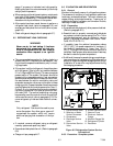
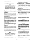
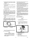
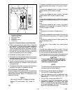
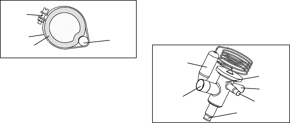
Unless the valve is defective, it seldom requires
maintenance other than periodic inspection to ensure
thatthe thermal bulb is tightlysecured tothe suctionline
and wrapped with insulating compound. (See
Figure 6-10.)
1
2
3
4
1. Suction Line
2. TXV Bulb Clamp
3. Nut and Bolt
4. TXV Bulb
Figure 6-10 Thermostatic Expansion Valve Bulb
6.14.1 Checking Superheat.
NOTE
Proper superheat measurement for the evapora-
tor expansion valve should be completed at
-- 1 8 _C(0_F) container box temperature where
possible. If the economizer valve is suspect, it
should be replaced.
a. Open the heater access panel (see Figure 2-1) to ex-
pose t he evaporator expansion valve.
b. Attach a temperature sensor near the expansion valve
bulb and insulate. Make sure the suction line is clean
and that firm contact is made with the sensor.
c. Connect an accurate gauge to the service port directly
upstream of the suction modulating valve.
d. Set the temperature set point to --18_C(0_F), and run
unit until conditions stabilize.
e. The readings may cycle from a high to a low reading.
Take readings of temperature and pressure every
three to five minutes for a total of 5or 6 readings
f. From the temperature/pressure chart (Table 6-7), de-
termine the saturation t emperature corresponding to
the evaporator outlet test pressures at the suction
modulation valve.
g. Subtract the saturation temperatures determined in
step f. from the temperatures measured in step e.. The
difference is the superheat of the suction gas. Deter-
mine the average superheat It should be 4.5 to 6.7 °C
(8 to 12 °F)
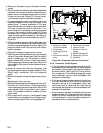
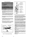
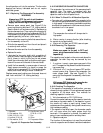
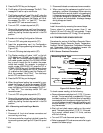
6.14.2 V alve Replacement
a. Removing the Expansion Valve
NOTES
1. TheTXV’sarehermeticvalvesanddonot
have adjustable superheat.
2. All connections on the evaporato r TXV are
bi---metallic, copper on the inside and
stainless on the outside. When brazing,
bi---metallic connections heat up very
quickly.
1
6
5
4
3
2
1. Evaporator Expansion Valve
2. Non-adjustable Superheat Stem
3. Equalizer Connection
4. Inlet Connection
5. Outlet Connection
6. Expansion Valve Bulb
Figure 6-11 Evaporator Expansion Valve