


6-19
T -309
6.24.2 Cracks
Cracks in the control box are repaired using a fiberglass
patch over the damaged area. Materials required are
included in theFiberglassPatchKitsuppliedwithCrack
Repair Kit, Carrier Transicold part number
76-00724-00SV (see Table 6-3).
a. The surface must be clean and dry. Roughen the sur-
face with sandpaper to ensure a good bond.
b. C ut the fiberglass cloth to allow a 25mm (1 --inch)
overlap around the area to be repaired.
c. Stretch and position the cloth over the area to be re-
paired and secure it with masking tape.
d. Make up sufficient epoxy glue to cover the cloth by
mixing equal parts of resin and hardener. Saturate the
cloth with the epoxy glue, spreading evenly.
e. Remove the tape and overlap the edge of the cloth
approximately 6 to 12 mm (1/4” to 1/2”) with glue.
f. Epoxy will dry in 45 --60 minutes. When completely
cured (12 hours), use sandpaper to smooth edges of
the patch.
6.24.3 Chips And Holes
Chips and holes in the control box are repaired using a
piece of aluminum or stainless steel to cover the
damaged area. Thematerial canbe cutto suit andriveted
in place. An adhesive sealant must be used to make the
repair watertight. The adhesive sealant (Sikaflex 221) is
included in Crack Repair Kit Carrier Transicold part
number 76-00724-00SV (see Table 6-3). Do not use an
acetone b ased silicone sealant (Which can be
identified by a vinegar--like odor).
a. To make up the patch, cut a piece of aluminum or
stainless steel so that it will overlap the damaged area
by at least 40 mm (1 1/2”) on all sides.
b. Choose rivet locations and drill the rivet holes in the
corresponding locations on the control box and patch
piece.
c. Apply the adhesive sealant around the damaged area
to form a seal between the control box and the patch
piece.
d. Rivet the patch piece in place.
e. File smooth any rough edges (including rivets) that
may come i nto contact with wires.
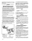
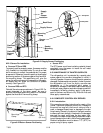
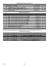
6.24.4 Inserts
The threaded brass inserts that are molded into the
control box will need to be replaced if t he threads
become stripped, or if the insert becomes loose. The
inserts and epoxy are contained in repair kit, Carrier
Transicold part number 76-50084-00 (see Table 6-4).
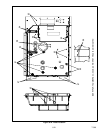
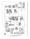
There are 6 different inserts used in the control box.
Refer to Figure 6-24 for the locations of the various
inserts.
NOTE
An epoxyapplicationgun isalso needed,Carri-
er Transicold part number 07 -- 00391 -- 00.
The damaged insert must be removed from the control
box. Table 6-5 identifies the drill size and drill depth to
beused for eachinsert. A stop ring should beused on the
drill bit to limit the depth.
a. Center the drill bit on the insert and drill to the pre-
scribed depth.
b. Remove the chips from the drilled hole.
c. Mix the two component epoxy and fill the hole 1/2
way to the top with epoxy.
d. Press the insert in until it is flush with the surface.
e. Wipe away any excess epoxy. The part is ready for
service after the bond material has hardened and is
tack free (approximately 20 minutes)
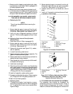
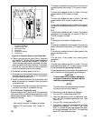
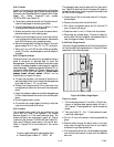
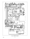
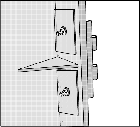
6.24.5 Door Hinge Inserts
If the door hinges have been pulled from the control box
drill and reinstall the hingeas shown in Figure 6-23 and
described in the following steps.
Figure 6-23 Door Hinge Repair
Materials needed:
1. Cut two square pieces of 3 mm thick (1/8 inch) alu-
minum or stainless steel approximately 40 mm (1
5/8”) square. These squares will serve as backing
plates.
2. Two nuts, bolts (10 -- 24 x 1”) and washers for each
insert that needs repair.
a. Drill a 1/4” hole in the center of each square backing
plate.
b. Pass the bolts through the bolts holes in the door
hinge, then through the control box at the l ocation
where the hinge insert pulled out.
c. From inside the control box, slide the backing plates
over the bolts and secure in place with the washers
and nuts.