


3-6T-309
1. Bulb mode code Cd35 is set to “Nor.”
2. Dehumidification code Cd33 is set to “Off.”
3. The user changes the set point to one
that is in the frozen range.
When bulb mode is disabled by any of the above, the
evaporator fan operation for dehumidification reverts to
“alt” and the DTS termination setting resets to the value
determined by controllerconfiguration variableCnF41.
3.3.10 Temperature Control -- Frozen Mode
With configuration variable CnF26 (Heat Lockout
Te mperature) set to --10_C the frozen mode ofoperation
is active with set points at or below --10_C(+14_F).
With the variable set to --5_C, the frozen mode is active
at or below --5_C(+23_F).
When in the frozen mode the controller maintains the
return air temperature at set point, the RETURN
indicator light willbe illuminatedonthe displaymodule
and the default reading on the display window will be
the return air probe reading.
When the return air temperature e nters the in-range
temperature tolerance as selected at function code
Cd30, the in-range light will energize.
3.3.11 Frozen Mode -- Conventional
Frozen range cargos are not sensitive to minor
temperature changes. The method of temperature
control employed in this range takes advantage of this
fact to greatly improve the energy efficiency of the unit.
Te mperature control in the frozen range is accomplished
by cycling thecompressoron andoffas theload demand
requires.
When cooling from a temperature that i s more than
2.5_C (4.5_F) above set point, t he system will be in the
frozen pull down mode. It will transition to economized
operation with a target SMV position of 100% open.
However, pressure and current limit functions may
restrict the valve, if either exceeds the preset value.
Once set point is reached, the unit will transition to the
frozen steady state mode. (Economized operation with
maximum allowed suction modulating valve opening.)
When temperature drops to set point minus 0.2_Cand
the compressor has run for at least fiveminutes, the unit
will transition to the frozen idle mode. The compressor
is turned off and the evaporator fans continue to run to
circulate air throughout the container. If temperature
rises above set point +0.2_C, the unit will transition
back to the frozen steady state mode.
If the temperature drops 10_C below set point, the unit
will transition to the frozen “heating” mode. In the
frozen heating mode the evaporator fans are brought to
high speed. The unit will transition back to the frozen
steady statemodewhen thetemperaturerisesbacktothe
transition point.
3.3.12 Frozen Mode -- Economy
In order t o activate economy frozen mode operation, a
frozen s et p oint temperature must be selected. The
economy mode is active when function codeCd34 is set
to “ON”. When economy mode frozen is active, the
system will perform normal frozen mode operations
except that the entire refrigeration system, excluding
the controller, will be turned off when the control
temperature is less than or equal to t he set point -- 2_C.
After an off-cycle period of 60 minutes, the unit will
turn on high speed evaporator fans for three minutes,
and then check the control temperature. If the control
temperature is greater than or equal to the set point +
0.2_C., the unit will restart the refrigeration system and
continue to cool until the previously mentioned
off-cycle temperature criteria are met. If the control
temperature is less than the set point + 0.2_C, the unit
will turn off the evaporator fans and restart another 60
minute off-cycle.
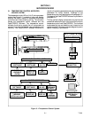
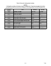
3.4 CONTROLLER ALARMS
Alarm display is an independent controller software
function. If an operating parameter is outside of
expected range or a components does not return the
correct signals back to the controller an alarm is
generated. A listing of the alarms is provided in
Table 3-6.
The alarm philosophy balances the protection of the
refrigeration unit and that of the refrigerated cargo. The
action taken when an error is detected always considers
the survival of the cargo. Rechecks are made to confirm
that an error actually exists.
Some alarms requiring compressor shutdown havetime
delays before and after to try t o keep the compressor on
line. An example is alarm code “LO”, (low main
voltage), when a voltage drop of over 25% occurs, an
indication is given on the display, but the unit will
continue to run.
When an Alarm Occurs:
a. The red alarm light will illuminate for alarm code
numbers 13, 17, 20, 21, 22, 23, 24, 25, 26, and 27.
b. If a detectable problem is found to exist, its alarm
code will be alternately displayed with the set point
on the left display.
c. The user should scroll through the alarm list to deter-
mine what alarms exist or have existed. Alarms must
be diagnosed and corrected before the Alarm List can
be cleared.
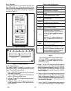
To Display Alarm Codes :
a. While in the Default Display mode, press the
ALARM LIST key. This accesses the Alarm List Dis-
playMode, whichdisplays anyalarmsarchived i n the
Alarm Queue.
b. The alarm queue stores up to 16 alarms in the se-
quence in which they occurred. The user may scroll
through the list by depressing an ARROW key.
c. The left display will show “AL##,” where ## is the
alarm number sequentially in the queue.
d. The right display will show the actual alarm code.
“AA##” will display for an active alarm, where “##”
is the alarm code. Or “IA##” will display for an inac-
tive alarm. S ee Table 3-6.