


3-2T-309
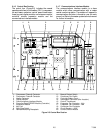
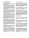
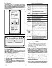
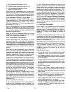
3.1.1 Key Pad
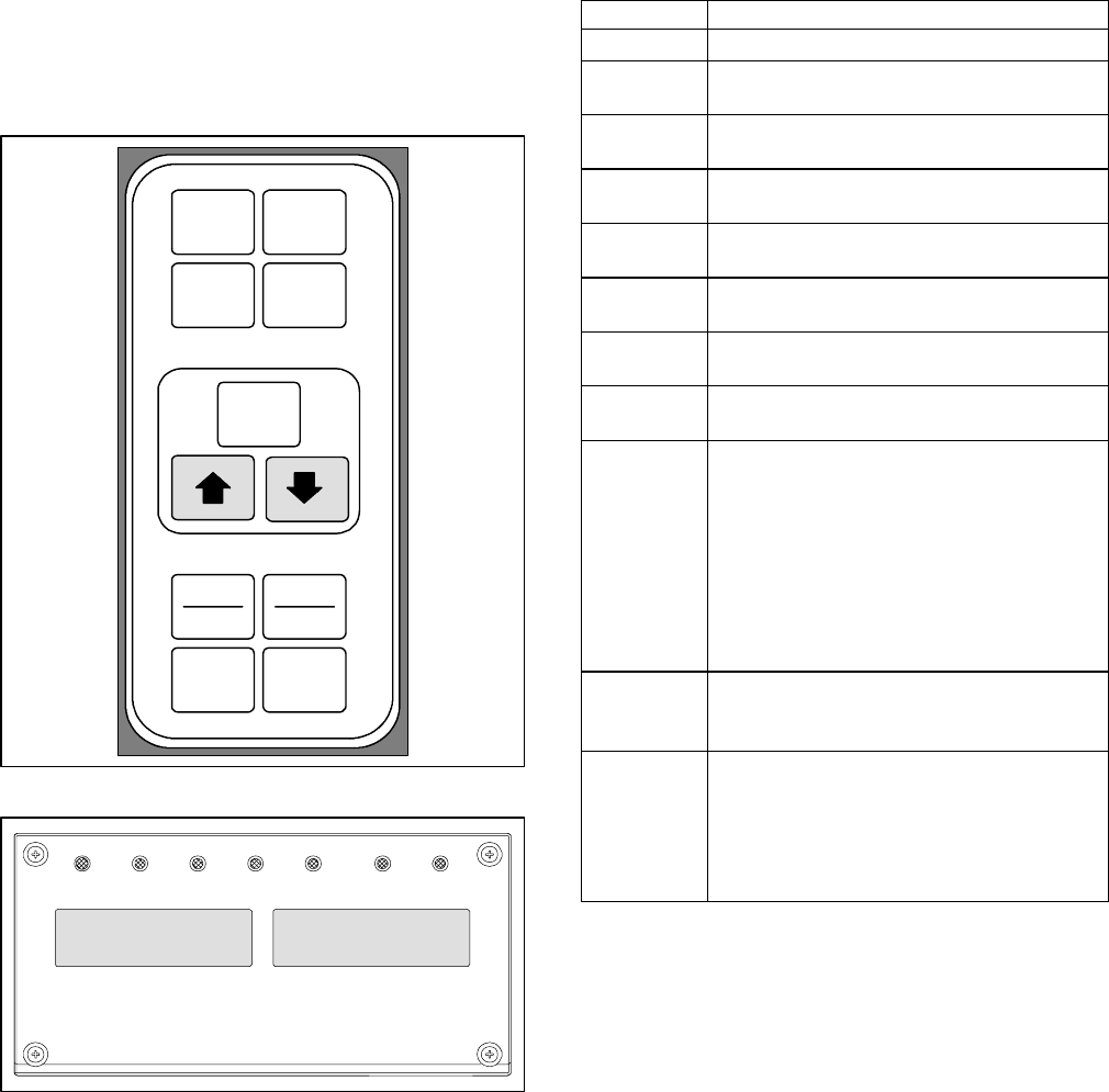
The key pad (Figure 3- 2) is mounted on the right-hand
side of the control box. The key pad consists of eleven
push button switches that act as theuser’s interface with
the controller. Descriptions of the switch functions are
provided in Table 3-1.
ENTER
BATTERY
POWER
DEFROST
INTERVAL
CODE
SELECT
PRE
TRIP
ALARM
LIST
ALT.
MODE
RETURN
SUPPLY
_C
_F
Figure 3- 2 Ke y Pad
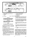
COOL HEAT DEFROSTIN RANGEALARM SUPPLY RETURN
SETPOINT/Code AIRTEMPERATURE/Data
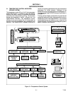
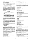
Figure 3- 3 Display Module
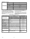
3.1.2 Display Module
The display module (Figure 3- 3) consists of two
backlighted five digit LCD displaysand sevenindicator
lights. The indicator lights include:
1. Cool -- White LED: Energized when the refrigerant
compressor is energized.
2. Heat -- Orange LED: Energized to indicate heater op-
eration in the heat or defrost mode.
3. Defrost -- Orange LED: Energized when theunit is in
the defrost mode.
4. In-Range -- Green LED: Energized when the con-
trolled temperature probe is within specified toler-
ance of set point.
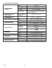
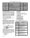
Table 3-1 Key Pad Function
KEY FUNCTION
Code Select Accesses function codes.
Pre-Trip
Displays the pre-trip selection menu. Dis-
continues pre-trip in progress.
Alarm List
Displays alarm list and clears the alarm
queue.
Defrost
Interval
Displays selected defrost interval.
Enter
Confirms a selection or saves a selection
to the controller.
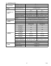
Arrow Up
Change or scroll a sel ection upward Pre-
trip advance or test interruption.
Arrow
Down
Change or scroll a sel ection downward.
Pre-trip repeat backward.
Return/
Supply
Displays non-controlling probe tempera-
ture (momentary display).
_C/_F
Displays alternate English/Metric scale
(momentary di splay). When set to _F,
pressure is displayed in psig and vacuum
in “/hg. “P” appears after the value to in-
dicate psig and “i” appears for inches of
mercury.
When set to _C. pressure readings are in
bars. “b” appears after the value to indi-
cate bars.
Battery
Power
Initiate battery backup mode to allow set
point and funct ion code selection if AC
power is not connected.
ALT Mode
This key is pressed to switch the functi ons
from the temperature software to the Da-
taCORDER Software. The remaining keys
function the same as described above ex-
cept the readings or changes are made to
the DataCORDER programming..
NOTE
The controlling probe in the perishable range
will be the SUPPLY air probe and the control-
ling probe in the frozen range will be the
RETURN air probe.
5. Supply -- Yellow LED: Energized whenthe supplyair
probe is used f o r control. Whe n this L ED is illumi-
nated, the tempera ture displaye d in the AIR TEMPER-
AT URE display is the rea ding at the supply air probe.
This LED will flash if dehumidification or humidifi-
cation is enabled.
6. Return -- Yellow LED: Energized when the return air
probe is used for contr ol. When this LED is illumi-
nated, the tempera ture displaye d in the AI R TEM-
PERATURE display is the reading at the return air pro-
be. This LED will flash if dehumidification or
humidification is enabled.
7. Alarm -- Red LED: Energized when there is an active
or an inactive shutdown alarm in the alarm queue