


6-6T-309
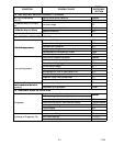
Table 6-1 Compressor Kit
Item
Component Qty
1 Compressor 1
2 Service Valve Seal 3
3 Mylar Washers 4
4 Wire Tie 2
5 Oil Sight Glass Plug 1
6 Resilient Mount 4
7 Upper Shock Mount Ring 1
8 Upper Shock Mount Bushing 1
9 Compressor Power Plug O--Ring 1
10 SST Washers 8
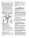
c. If the compressor is not operational, turn the unit
start--stop switch (ST) and unit circuit breaker
(CB--1) OFF. Disconnect power to theunit and front--
seatthe discharge, suction, economizer,and oil return
service valves.
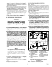
Remove all remaining refrigerant from the compres-
sor using a refrigerant recovery system. Connect
hoses to suction, economizer and discharge service
valves ports. Evacuate compressor to 500 microns
(75.9 cm Hg vacuum = 29.9 inches Hg vacuum).
d. Make sure power to the unit is OFF and unit power
plug disconnected. Disconnect the power plug from
the compressor.
e. Loosen and break the seal at fittings from the suction,
discharge, economizer, and the oil return service
valves. Remove fittings and discard service valve
seals, retain oil return valve O--ring.
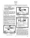
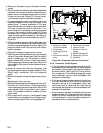
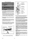
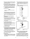
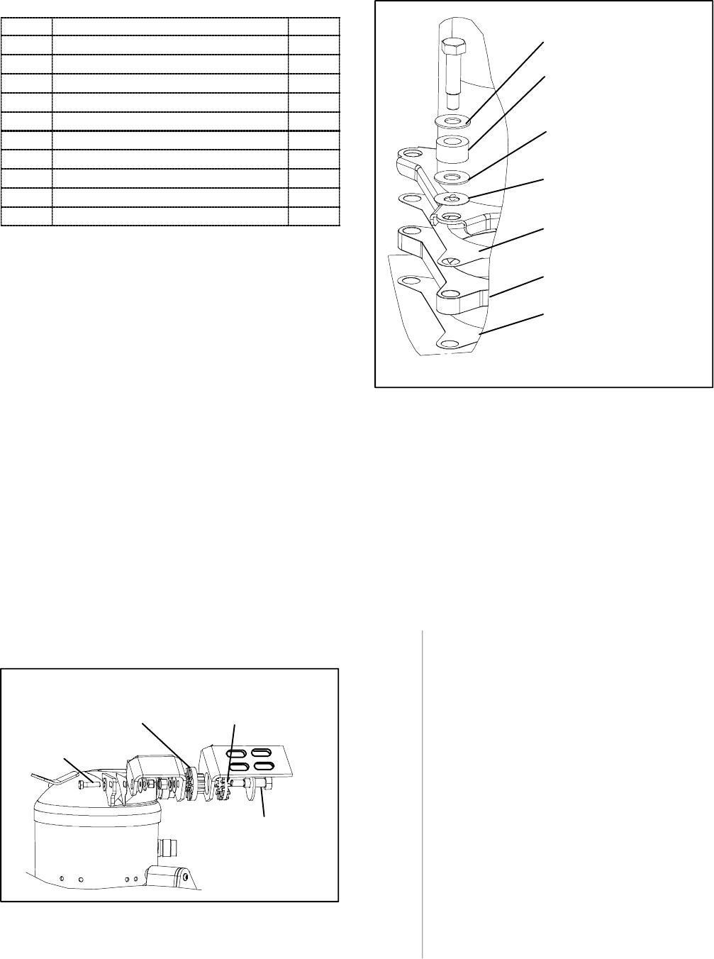
f. Remove the entire compressor upper mounting
bracket assembly,(see F igure 6-7) by removing the
fourcapscrewsattachingit t o the unit and the 32--mm
bolt from the compressor mounting bracket.
Upper Shock Mount
Bushing(KitItem8)
Upper Shock Mount
Ring (Kit Item 7)
Shoulder Bolt
32mm Bolt
Figure 6-7 Compressor Upper Mounting
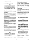
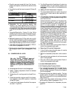
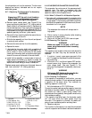
Resilient Mount
(Kit Item 6)
Mylar Washer
(Kit Item 3)
Mylar Protector
(Retain)
Base Plate
(Retain)
Mylar Protector
(Retain)
SST Washer
(Kit Item 10)
SST Washer
(Kit Item 10)
Figure 6-8 Compressor Lower Mounting
g. Replace the upper mounting bracket shock mount
ring and bushing (kit items 7and 8). Reassemble the
bracket in the same manner as the original and torque
the shoulder bolt to 2.8 mkg (20 ft--lbs.).
h. Remove the male coupling from the top of t he sight
glass on the old compressor and hand assemble to the
oil return valve coupling for safe keeping. Plug the
top of the replacement compressor sight glass with
the plug (kit item 5) to prevent spilling oil.
i. Remove the lower mounting bolts and hardware (see
Figure 6-8). Using plugs from replacement compres-
sor, plug connections on old compressor. Removethe
old compressor. Refer to paragraph 2.2for compres-
sor weight. Return plugs to replacement compressor.
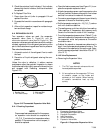
j. The replacement compressor is shipped with an oil
charge of 591ml (20 ounces). Before sliding t he new
compressori n the unit, removetheoil sight glassplug
and (using a small funnel) charge the compressor
with an additional 1893ml (64 ounces) Castrol--Ice-
maticSW20(POE oil).Reassembletheoilsight glass
plug toavoid spilling oilwhensliding thecompressor
in the unit.
k. Secure the base plate and mylar protectors to the com-
pressor with wire ties (kit item 4), and place the com-
pressor in the unit.
l. Cut and remove the wire ties that were used to hold
the base plate and protectors to the compressor. Us-
ing new resilient mounts, SST washers and mylar
washers (kit items 3, 6 & 10). Install the four mount-
ing screws loosely.
m.Install themalecoupling (removedin step h.) into the
sight glass port.