


6-3
T -309
gauge. If a vacuum is indicated, emit refrigerant by
crackingthe liquidline valvemomentarilyto buildup
a slight positive pressure.
g. When openingup the refrigerantsystem, certainparts
may frost. Allow the part to warm to ambient temper-
ature before dismantling. This avoids internal con-
densation which puts moisture in the system.
h. After repairs have been made, be sure to perform a
refrigerant leak check (refer to paragraph 6.5), and
evacuate and dehydrate the low side (refer to para-
graph 6. 6).
i. Check refrigerant char ge (refer to paragraph 6.7).
6.5 R EFRIGERANT LEAK CHECKING
WARNING
Never use air for leak testing. It has been
determined that pressurized, air-rich mix-
tures of refrigerants and air can undergo
combustion when exposed to an ignition
source.
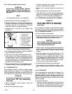
a. The recommended procedure for finding leaks in a
systemis with a R-134aelectronicleak detector. Test-
ing joints with soapsuds is satisfactory only for locat-
ing large leaks.
b. If the system is without refrigerant, charge the system
with refrigerant 134a to build up pressure between
2.1 to 3.5 kg/cm@ (30 to 50 psig). To ensurecomplete
pressurization of the system, refrigerant should be
charged at the compressor suction and economizer
service valves and the liquid line service valve. Also,
the area between the suction modulating valve and
evaporator expansion valve may not be open to these
charging points. P ressure between these components
may be checked at the low side access valve (item 11,
Figure 2-2) or by checking t hat the suction modulat-
ing valve is more than 10% open at controller func-
tion code Cd01. The suction modulating valve may
beopened byuse ofthe controller function codeCd41
valve override control (refer to paragraph 6.19). Re-
move refrigerant cylinder and leak-check all connec-
tions.
NOTE
Only refrigerant 134a should be used to pres-
surize the system. Any other gas or vapor will
contaminate the system, which will require
additional purging and evacuation of the sys-
tem.
c. If required, remove refrigerant using a refrigerant
recovery system and repair any leaks.
d. Evacuate and dehydrate the unit. (Refer to paragraph
6.6.)
e. Charge unit per paragraph 6.7.
6.6 EVACUATION AND DEHYDRATION
6.6.1 General
Moisture is the deadly enemy of refrigeration systems.
The presence of moisture in a refrigeration system can
have many undesirable effects. The most common are
copper plating, acid sludge formation, “freezing-up” of
metering devices by free water, and formation of acids,
resulting in metal corrosion.
6.6.2 Preparation
a. Evacuate and dehydrate only after pressure leak test.
(Refer to paragraph 6.5.)
b. Essential tools to properly evacuate and dehydrate
any system include a vacuum pump (8 m
3
/hr = 5 cfm
volume displacement) and an electronic vacuum
gauge. (The pump i s available from Carrier Trans-
icold, P/N 07-00176-11.)
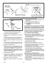
c. If possible, keep the ambient temperature above
15.6_C(60_F) to speed evaporation of moisture. If
the ambient temperature is lower than 15.6_C
(60_F), ice might form before moisture removal is
complete. Heat lampsor alternate sourcesofheatmay
be used to raise the system temperature.
d. Additional time may be saved during a completesys-
tem pump down by replaceing the filter-drier with a
section of copper tubing and the appropriate fittings.
Installation of a new drier may be performed during
the charging procedure.
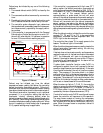
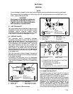
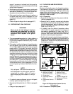
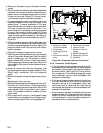
6
4
5
D
S
2
3
11
9
10
1
7
8
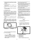
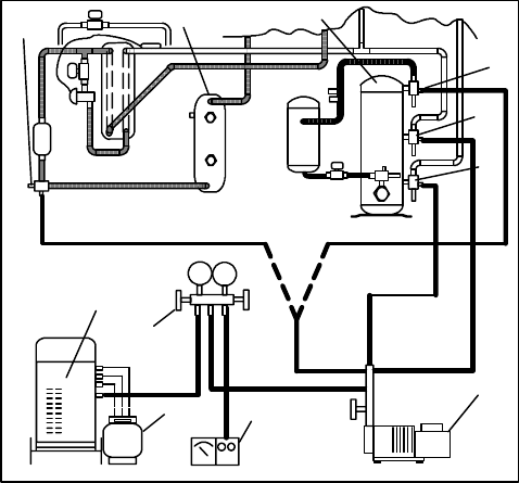
1. Liquid Service Valve
2. Receiver or Water
Cooled Condenser
3. Compressor
4. Discharge Service
Valve
5. Economizer Service
Valve
6. Suction Service Valve
7. Vacuum Pump
8. Electronic Vacuum
Gauge
9. Manifold Gauge Set
10. Refrigerant Cylinder
11. Reclaimer
Figure 6-5. Refrigeration System Service
Connections
6.6.3 Procedure - Complete system