


3-8T-309
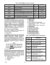
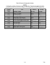
Table 3-2 DataCORDER Configuration Variables
CONFIGURATION NO.
TITLE DEFAULT OPTION
dCF01 (Future Use) -- -- -- --
dCF02 Sensor Configuration 2 2,5,6,9,54,64,94
dCF03 Logging Interval (Minutes) 60 15,30,60,120
dCF04 Thermistor Format Short Low, Normal
dCF05 Thermistor Sampling Type A A,b,C
dCF06 Controlled Atmosphere/Humidity Sampling Type A A,b
dCF07 Alarm Configuration USDA Sensor 1 A Auto, On, Off
dCF08 Alarm Configuration USDA Sensor 2 A Auto, On, Off
dCF09 Alarm Configuration USDA Sensor 3 A Auto, On, Off
dCF10 Alarm Configuration Cargo Sensor A Auto, On, Off
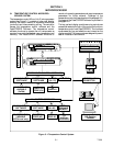
b. Configuration Software
The configuration software controls the recording and
alarm functions of the DataCORDER. Reprogramming
to the factory installed configuration is achieved via the
same configuration card as the unit control module
software. Changes to the unit DataCORDER
configuration may be made made using the Data Vi ew
integration device. A listing of the configuration
variables is provided in Table 3-2. Descriptions of
DataCORDER operation for each variable setting are
provided in the following paragraphs.
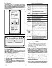
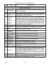
3.6.3 Sensor Configuration (dCF02)
Two modes of operation may be configured, the
Standard Mode and the Generic Mode.
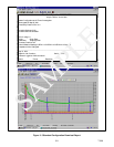
a. Standard Mode
In the standard mode, the user may configure the
DataCORDER to record data using one of seven
standard configurations. Standard configuration
variables, with descriptions, are listed in Table 3-3.
The six thermistor inputs (supply, return, USDA #1, #2,
#3 and cargo probe) and the humidity sensor input will
be generated by the DataCORDER. An example of a
report using a standard configuration is shown in
Figure 3- 5.
NOTE
The DataCOR DER software uses the supply
and return recorder
sensors (SRS,RRS). The
temperature control software uses the supply
and return temperature
sensors (STS,RTS) .
b. Generic Mode
The generic recording mode allows user selection of the
network data points to be recorded. The user may select
up to a total of eight data points for recording. A list of
the data points available for recording follows.
Changing the configuration to generic and selecting
which data points to record may be done using the
Carrier Transicold Data Retrieval Program.
1. Control mode
2. Control temperature
3. F requency
4. Humidity
5. Phase A current
6. Phase B current
7. Phase C current
8. Main voltage
9. Suction modulation valve percentage
10. Discrete outputs (Bit mapped -- require special
handling if used)
11. Discrete inputs (Bit mapped -- require special
handling if used)
12. Ambient sensor
13. Compressor suction sensor
14. Compressor discharge sensor
15. Return temperature sensor
16. Supply temperature sensor
17 Defrost temperature sensor
18. Discharge pressure transducer
19. Suction pressure transducer
20. Condenser pressure transducer
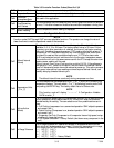
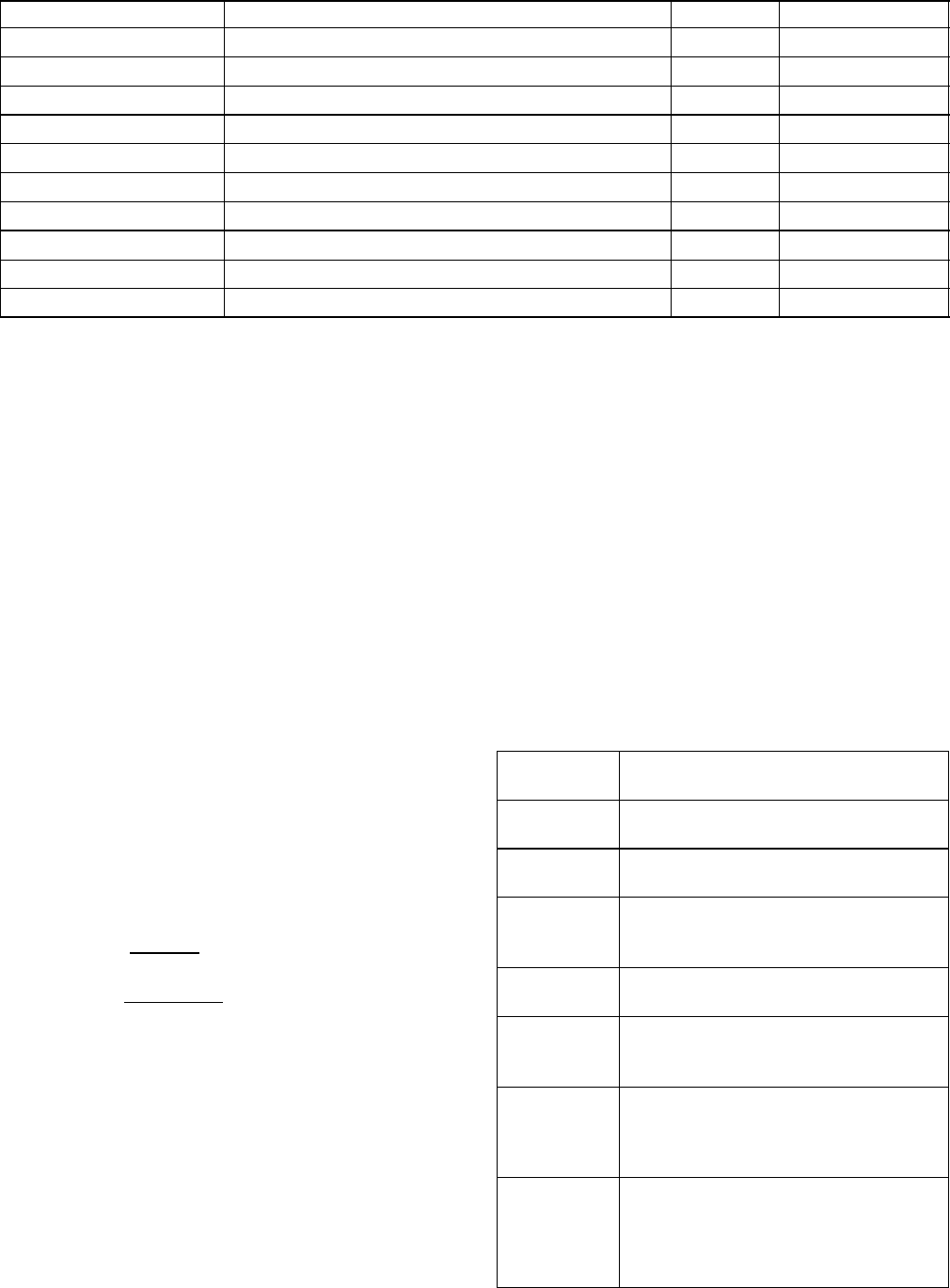
Table 3-3 DataCORDER Standard Configurations
Standard
Config.
Description
2sensors
(dCF02=2)
2 thermistor inputs(supply & return)
5sensors
(dCF02=5)
2 thermistor inputs(supply & return)
3 USDA thermistor inputs
6sensors
(dCF02=6)
2 thermistor inputs(supply & return)
3 USDA thermistor inputs
1 humidity input
9sensors
(dCF02=9)
Not Applicable
6sensors
(dCF02=54)
2 thermistor inputs(supply & return)
3 USDA thermistor inputs
1 cargo probe (thermistor input)
7sensors
(dCF02=64)
2 thermistor inputs(supply & return)
3 USDA thermistor inputs
1 humidity input
1 cargo probe (thermistor input)
10 sensors
(dCF02=94)
2 thermistor inputs(supply & return)
3 USDA thermistor inputs
1 humidity input
1 cargo probe (thermistor input)
3 C.A. inputs (NOT APPLICABLE)