


6-8T-309
6.10.2 Checking High Pressure Switch
WARNING
Do not u se a nitrogen cylinder without a
pressure regulator. Do not use oxygen in or
near a refrigeration system as an explosion
may occur.
NOTE
The high pressure switch is non-adjustable.
a. Remove switch as outlined in paragraph 6.10.1
b. Connect ohmmeter or continuity light across switch
terminals. Ohm meter will indicate no resistance or
continuity light will be illuminated if the switch
closed after relieving compressor pressure.
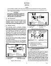
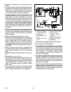
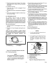
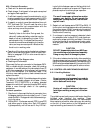
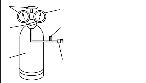
c. Connect hose to a cylinder of dry nitrogen. (See
Figure 6-9.)
1. Cylinder Valve
and Gauge
2. Pressure Regulator
3. Nitrogen Cylinder
4. Pressure Gauge
(0 to 36 kg/cm@ =
0 to 400 psig)
5. Bleed-Off Valve
6. 1/4 inch Connection
1
2
3
4
5
6
Figure 6-9 High Pressure Switch Testing
d. Set nitrogen pressure regulator at 26.4 kg/cm@ (375
psig) with bleed-off valve closed.
e. Close valve on cylinder and open bleed-off valve.
f. Open cylinder valve. Slowly close bleed-off valve to
increase pressure on switch. The switch should open
at a static pressure up to 25 kg/cm@ (350 psig). If a
light is used, light willgo out.If an ohmmeter is used,
the meter will indicate open circuit.
g. Slowly open bleed-off valve to decrease the pressure.
The switch should close at 18 kg/cm@ (250 psig).
6.11 CONDENSER COIL
The condenser consists of a s eries of parallel copper
tubes expanded into copper fins. The condenser coil
must becleaned withfresh water or steam so the airflow
is not restricted. To replace the coil, do the following:
WARNING
Do not open the condenser fan grille before
turning power OFF and disconnecting
power plug.
a. Using a refrigerant reclaim system, remove the
refrigerant charge.
b. Remove the condenser coil guard.
c. Unsolder discharge line and remove the line to t he
receiver or water-cooled condenser.
d. Remove coil mounting hardware and remove the
coil.
e. Install replacement coil and solder connections.
f. Leak-check the coil connections per paragraph para-
graph 6.5. Evacuate the unit per paragraph 6.6 then
charge the unit with refrigerant per paragraph 6.7.
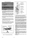
6.12 CONDENSER FAN AND MOTOR ASSEMBLY
WARNING
Do not open condenser fan grille before
turning power OFF and disconnecting
power plug.
The condenser fan rotates counter-clockwise (viewed
from front of unit), pulls air through the the condenser
coil, and discharges horizontally throughthe front ofthe
unit. To replace motor assembly:
a. Open condenser fan screen guard.
b. Loosen two square head set screws on fan. (Thread
sealer has been applied to set screws at installation.)
Disconnect wiring from motor junction box.
CAUTION
Take necessary steps (place plywood over
coil or use sling on motor) to p revent motor
from falling into condenser coil.
c. Remove motor mounting hardware and replace the
motor. It is recommended that new locknuts be used
when replacing motor. Connect wiring per wiring
diagram.
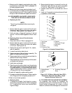
d. Install fan loosely on motor shaft (hub side in). DO
NOT USE FORCE. If necessary,tap thehub only, not
the hub nuts or bolts. Install venturi. Apply “Loctite
H” to fan set screws. Adjust fan within venturi so that
the outer edge of the fan is within 2.0 ± .07 mm
(0.08” ¦ 0.03”) from the outside of the orifice open-
ing. Spin fan by hand to check clearance.
e. Close and secure condenser fan screen guard.
f. Apply power to unit and check fan rotation. If fan
motor rotates backward, reverse wire numbers 5 and
8.
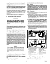
6.13 FILTER-DRIER
On units equipped with a water-cooled condenser, if the
sight glass appears to be flashing or bubbles are
constantly moving through the sight glass when the
suction modulation valve is fully open, the unit may
have a l ow refrigerant charge or the filter-drier could be
partially plugged.
a. To Check Filter-Drier
1. Test for a restricted or plugged filter-drier by feeling
the liquid line inlet and outlet connections of the
drier cartridge. If the outlet side feels cooler than the
inlet side, then the filter-drier should be changed.