


6-7
T -309
n. Place the new service seals (kit item 2) at the com-
pressor service ports, connect the four service valves
loosely.
o. Torque the fourresilient mount screws to 6.2 mkg(45
ft--lbs).
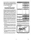
p. Torque the four service valves to:
Service V alve Torque
Suction or Discharge 11 to 13.8 mkg
(80 to 100 ft--lbs.)
Economizer 6.9to8.3mkg
(50to60ft--lbs.)
Oil Return 1.4to1.66mkg
(10to12ft--lbs.)
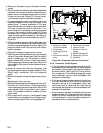
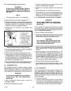
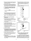
q. Reassemble the top mounting bracket (see
Figure 6-7) by hand tightening the 32--mm (1¼
--inch) bolt and torquing the four mounting screws to
0.9 mkg (6.5 ft--lbs). Align the mounting so that the
ring and bushing assembly are free with no compres-
sion.
r. Torque the 32mm bolt to 1.5 mkg (11 ft--lbs. ). While
maintaining the free movement of the shock mount,
torque the four mounting screws to 0.9 mkg (6.5 ft--
lbs.).
s. R eplace the power plug O--Ring with new ring (kit
item 9). Insert the power plug into thecompressor fit-
ting. Be sure plug is fully seated into the fitting and
then thread the coupling nut a minimum of 5 turns.
t. Leak check and evacuate the compressor to 1000 mi-
crons. Refer to paragraphs
6.5 and 6.6
u. Run the unit for at least 15 minutes and check the oil
and refrigerant levels. Refer to paragraphs 6.7 and
6.9.
6.9 COMPRESSOR OIL LEVEL
CAUTION
Use only Carrier Transicold approved
Polyol Ester Oil (POE) -- Mobil ST32 com-
pressor oil with R-134a. Buy in quan tities of
one quartor smaller. When using this hygro-
scopic oil, immediately reseal. Do not leave
container of oil open or contamination will
occur.
a. Checking the Oil Level in the Compressor
1 Ideally, ambient temperature should be between
40_F and 100_ F.
2 Operate the unit in cooling mode for at least 20 min-
utes.
3 C heck the controller function code Cd1 for the suc-
tion modulation valve (SMV) position. It should be
at least 20% open.
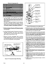
4 Locate the oil sight glass on t he side of the compres-
sor (item
7, Figure 2-3).
5 Turn Start/Stop switch offand allowoil to draininto
compressor sump. Oil level must be visible in the
sight glass. Ifit is notvisible, oil must beaddedtothe
compressor.
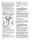
b. Adding Oil with Compressor in System
1. The recommended method is to add oil using an oil
pump at the oil return service valve (see item
15,
Figure 2-3
)
2. In an emergency where an oil pump is not available,
oil m ay bedrawn i nto the compressorthrough the oil
return service valve.
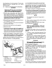
Connect the suction connection of the gauge man-
ifold to the compressor oil return valve port, and
immerse the common connection of the gauge man-
ifold in an open container of refrigeration oil.
Extreme care must be taken to ensure the manifold
common connection remains immersed in oil at all
times. Otherwiseair and moisture will be drawn into
the compressor. Crack the oil return service valve
andgauge valveto venta small amountof refrigerant
through the common connection and theoil to purge
the lines of air. Cl ose the gauge manifold valve.
With the unit running, turn the suction service valve
toward frontseat and induce a vacuum in the com-
pressor crankcase. Do not allow the compressor to
pull below 127mm/hg (5 “/hg). SLOWLY crack the
suction gauge manifold valve and oil will flow
throughthe oil return servicevalveinto thecompres-
sor. Add oil as necessary.
3 R un unit for 20 minutes in cooling mode. Check oil
level at the compressor sight glass.
c. Removing Oil from the Compressor:
1 If the oil level is above the sight glass, oil must be
removed from the compressor.
2 Perform a compressor pump down, refer to section
6.4.
3 Remove theoil plug, and drain oil until a level can be
seen in the sight glass.
4 R un unit for 20 minutes in cooling mode. Check oil
level at the compressor sight glass.
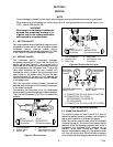
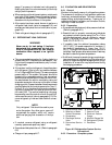
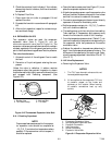
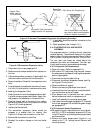
6.10 HIGH PRESSURE SWITCH
6.10.1 Replacing High Pressure Switch
a. Turn unit start-stop switch OFF. Frontseat the suc-
tion, discharge, economizer and oil return service
valves to isolate compressor. Remove the refrigerant
from the compressor.
b. Disconnect wiring from defective switch. The high
pressure switch is located on the discharge service
valve and is removed by turning counterclockwise.
(See Figure 2-3.)
c. Install a new high pressure switch a fter verifying
switch settings. (Refer t o paragraph 6. 10.2.)
d. Evacuate and dehydrate the compressor per para-
graph 6. 6.