


Note: Unit-mounted starters do not have to be megohm tested.
10. Tighten up all wiring connections to the plugs on the SMM, 8-input, and PSIO modules.
11. Ensure that the voltage selector switch inside the power panel is switched to the incoming
voltage rating.
12. On machines with freestanding starters, inspect the power panel to ensure that the
contractor has fed the wires into the bottom of the panel. Wiring into the top of the panel can
cause debris to fall into the contactors. Clean and inspect the contactors if this has
occurred.
Carrier Comfort Network Interface
The Carrier Comfort Network (CCN) communication bus wiring is supplied and installed by
the electrical contractor. It consists of shielded, 3-conductor cable with drain wire.
The system elements are connected to the communication bus in a daisy chain
arrangement. The positive pin of each system element communication connector must be wired
to the positive pins of the system element on either side of it; the negative pins must be wired to
the negative pins; the signal ground pins must be wired to signal ground pins.
To attach the CCN communication bus wiring, refer to the certified drawings and wiring
diagrams. The wire is inserted into the CCN communications plug (COMM1) on the PSIO
module. This plug also is referred to as J5.
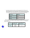
Note: Conductors and drain wire must be 20 AWG (American Wire Gage) minimum stranded,