


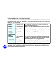

If all modules indicate communications failure, check communications plug on the PSIO
module for proper seating. Also check the wiring (CCN bus — 1:red, 2:wht, 3:blk; Sensor bus —
1:red, 2:blk, 3:clr/wht). If a good connection is assured and the condition persists, replace the
PSIO module.
If only one 8-input module or SMM indicates communication failure, check the
communications plug on that module. If a good connection is assured and the condition
persists, replace the module.
All system operating intelligence rests in the PSIO module. Some safety shutdown logic
resides in the SMM in case communications are lost between the 2 modules. The PSIO
monitors conditions using input ports on the PSIO, the SMM, and the 8-input modules. Outputs
are controlled by the PSIO and SMM as well.
3. Power is supplied to modules within the control panel via 21-vac power sources.
The transformers are located within the power panel, with the exception of the SMM, which
operates from a 24-vac power source and has its own 24-vac transformer located within the
starter.
Within the power panel, T1 supplies power to the LID, the PSIO, and the 5-vac power sup-
ply for the transducers. The other 21-vac transformer is T4, which supplies power to both 8-
input modules (if present). T4 is capable of supplying power to two modules; if additional
modules are added, another power supply will be required. Power is connected to Termi-
nals 1 and 2 of the power input connection on each module.