


326142000
6
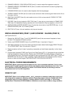
2. SPANNER WRENCH, FLOW REGULATORS (item 2) is used to adjust flow regulators inside Unit.
3. SPANNER WRENCH, DISPENSING VALVE (item 3) is used to remove shank nuts securing dispensing
valves to faceplates.
4. CLEANING BRUSH (item 4) is used to clean faceplate relief valves passages.
5. TAPERED GASKET, BLACK (item 5) is used to seal connection when connecting plain water source line to
Unit water inlet line.
6. DRIP TRAY SUPPORTS (item 8) to be installed on front of Unit and secured with THREAD CUTTING
SCREWS (item 9).
7. CUP REST (item 6) to be installed in DRIP TRAY (item 7), then drip tray to be installed in FRAME, DRIP
TRAY (item 13). Assembled drip tray assembly then to be installed on drip tray supports on front of Unit.
8. INSTRUCTIONS, SCRAPER BLADES (item 10) pictorially shows how to install BEATERS (item 11) and
SCRAPER BLADES (item 12) in freeze cylinders.
9. DRIP TRAY KIT (item 14) to be installed on drip tray as instructed.
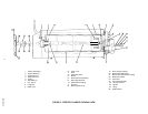
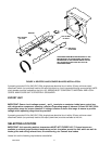
INSTALLING BEATERS (ITEM 11) AND SCRAPER BLADES (ITEM 12)
(see Figures 3 and 4)
1. Remove four HEX NUTS (item 7) and FLATWASHERS (item 6) that secure each faceplate to freeze
cylinders. Pull faceplates off freeze cylinders.
2. Position two SCRAPER BLADES (item 12) on BEATER (item 11 as shown in Figure 4.
3. Slide beater assembly into one of the freeze cylinders so beater slotted hooks engage DRIVE PIN (item
17) on DRIVE SHAFT (item 14) as shown in Figure 3.
4. Repeat procedure outlined in step 3 preceding to assemble and install beater assembly in other freeze
cylinder.
5. Lubricate each faceplate O-RING (see Figure 3 with Dow-Corning (DC 111) light grade silicone to facilitate
installing faceplates on freeze cylinders. Position each FACEPLATE On freeze cylinders so dispensing
valves faucets face down. Secure each faceplate to freeze cylinder with four HEX NUTS (item 7) and FLAT
WASHERS (item 6) removed in step 1 preceding. Tighten HEX NUTS until faceplates touch all the way
around on freeze cylinder flanges. CAUTION-DO NOT OVERTIGHTEN HEX NUTS.
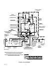
ELECTRICAL POWER REQUIREMENTS
IMPORTANT: Before connecting electrical power to Unit, refer to nameplate and Note if Unit is to be
operated with 50 or 60 Hz power source and also note beaters motors manufacturer. No. 6, No. 7, and
No. 8 switches on DIP switch assembly on master circuit board must be set according to motors
manufacturer and for 50 or 60 Hz operation.
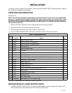
DOMESTIC UNIT
IMPORTANT: Power circuit voltage across L
1
and L
2
terminals on contactor inside lower control box,
with refrigeration compressor operating, must be in operating range of between 219/242 VAC, 60 Hz
single-phase range for proper operation. If voltage is below or above this range, a .75 KVA Step
Up/Step Down Transformer (P/N 326138000) is available to correct below or above voltage condition.