


10326142000
WARNING: CO
2
displaces oxygen. Strict attention must be observed in the prevention of
CO
2
(carbon dioxide) gas leaks in the entire CO
2
and soft drink system. If a CO
2
gas leak is
suspected, particularly in a small area, immediately ventilate the contaminated area before
attempting to repair the leak. Personnel exposed to high concentration of CO
2
gas will experience
tremors which are followed rapidly by loss of consciousness and suffocation.
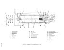
1. Unscrew protector cap (with chain attached) from CO
2
cylinder valve. Open CO
2
cylinder valve slightly
counterclockwise to blow any dirt or dust from outlet fitting before installing primary CO
2
regulator, then
close valve.
2. Remove shipping plug from primary CO
2
regulator assembly coupling nut and make sure gasket is in place
inside nut. Install regulator assembly on CO
2
cylinder so gages can be easily read, then tighten coupling
nut. DO NOT OPEN CO
2
CYLINDER VALVE AT THIS TIME.
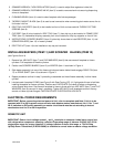
CONNECTING SOFT DRINK TANKS CO
2
LINES TO PRIMARY CO
2
REGULATOR
ASSEMBLY
(see Figure 2)
1. Connect soft drink tanks CO
2
lines to primary CO
2
regulator manifold assembly as shown in Figure 2.
2. Install gas quick disconnects on ends of soft drink tanks CO
2
lines. DO NOT CONNECT CO
2
LINES TO
TANKS AT THIS TIME.
PREPARING UNIT SYRUP INLET LINES FOR CONNECTION TO SOFT DRINK TANKS
(see Figure 2)
1. Route Unit syrup inlet lines, labeled No. 1 and No. 2, out through hole provided in Unit base to soft drink
tanks location.
2. Install liquid disconnects on ends of Unit syrup inlet lines. DO NOT CONNECT SYRUP LINES TO TANKS
AT THIS TIME.
CONNECTING PLAIN WATER INLET SUPPLY LINE TO UNIT
(see Figure 2)
NOTE: IMI Cornelius Inc. recommends that a water shutoff valve and water filter be installed in plain
water inlet supply line (see Figure 2). A Cornelius Water Filter (P/N 313860000) and Quick Disconnect
Set (P/N 313867000) are recommended.
1. Before connecting plain water inlet supply line to Unit, open shutoff valve in water supply line for a period of
time to flush out any metal shavings.
2. Route water inlet line out through hole in bottom of Unit base.
NOTE: Carbonator plain water inlet adjustable water pressure regulator (see Figure 12) is factory
adjusted to 45-psi and should not be readjusted.
3. Connect Unit water inlet line to plain water inlet supply line (12-psi minimum pressure). Seal connection
with TAPERED GASKET, BLACK (item 5). DO NOT OPEN WATER INLET SUPPLY LINE SHUTOFF
VALVE AT THIS TIME.