


11 326142000
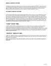
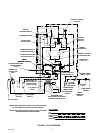
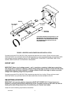
CONNECTING ELECTRICAL POWER CIRCUIT TO UNIT
(see Figure 17)
WARNING: Make sure Unit 30-amp minimum-rated disconnect switch (not provided) or
equivalent HACR circuit breaker is in ‘‘OFF’’ position.
Domestic Unit.
IMPORTANT: Power circuit voltage across L
1
and L
2
terminals on contactor inside lower control box,
with refrigeration compressor operating, must be in operating range of between 219 and 242 VAC, 60Hz
single-phase range for proper operation. If voltage is below or above this range, a .75 KVA Step
Up/Step Down Transformer (P/N 326138-000) is available to correct below or above voltage condition.
Use No. 10 AWG copper wire, or larger, depending upon line length, in suitable conduit or BX sheath.
POWER CIRCUIT TO UNIT MUST BE MADE UP OF COPPER CONDUCTORS AND ALL WIRING MUST
CONFORM TO NATIONAL AND LOCAL CODES.
Export Unit.
IMPORTANT: Power circuit voltage across L
1
and L
2
terminals on contactor inside lower control box,
with refrigeration compressor operating, must be in operating range of between 219 and 242 VAC, 50Hz
single-phase range for proper operation. If voltage is below or above this range. A means to provide
voltage within operating range must be provided.
1. Remove lower control box (located on lower-right side facing front of Unit) cover for access to contactor L
1
and L
2
terminals.
WARNING: This Unit must be electrically grounded to avoid possible fatal electrical shock
or serious injury to the operator. A green screw, with lock washer, is provided inside
control box to connect power circuit ground wire electrically grounding the Unit.
2. Connect electrical power from 30-amp minimum-rated disconnect switch (not provided) fused at 30-amps
(slo-blow) or through an equivalent HACR circuit breaker to L
1
and L
2
terminals on contactor inside control
box. MAKE SURE GROUND WIRE IS CONNECTED TO GREEN GROUND SCREW INSIDE CONTROL
BOX.
3. Install lower control box cover and secure with screws.
PREPARATION FOR OPERATION
50 OR 60 HZ OPERATION AND BEATER MOTOR SELECT
IMPORTANT: Before connecting electrical power to Unit, refer to Unit nameplate and note if Unit is to
be operated with 50 or 60 Hz electrical power and also note beater motor manufacturer’s name. No. 6,
No.7, and No. 8 switches on DIP switch assembly on master circuit board must be set according to
motor manufacturer and for 50 or 60 Hz operation as follows.
1. Remove four screws securing Unit upper control box cover, then remove cover for access to the master
circuit board (see Figure 10).
2. After noting if Unit is to be operated with 50 or 60 Hz electrical power and beater motors manufacturer’s
name, refer to Figure 10 and Table 5 to place DIP switch assembly No. 6, No. 7, and No. 8 switches in
appropriate positions.