


29
326142000
7. Remove parts from sanitizing solution and place on clean paper towels.
NOTE: Use Dow-Corning DC-111 (P/N 321471000) light grade silicone lubricant.
8. Assemble dispensing valve as follows:
A. Lubricate caged O-ring. Carefully install caged O-ring on valve from straight end (opposite tapered
end). Lubricate grooves in which O-ring rides to fill in all void areas around O-ring.
B. Carefully install valve with caged O-ring in dispensing valve body.
C. Install spring fitting, knob and lever parts, torsion spring, and spring housing assembly by reversing
removal procedure. Do not tighten down hold-down plates securing spring housing at this time.
D. Turn spring housing to the left (counterclockwise) to put tension on torsion spring, then tighten
hold-down plates to secure spring housing.
E. Test dispensing valve to make sure it closes by itself when lever is released. If not, readjust torsion
spring tension.
9. Thoroughly clean RELIEF VALVE (item 9), then screw relief valve into FACEPLATE (item 8).
10. Service beater drive shaft seal assembly as follows:
NOTE: Use Dow-Corning DC-111 (P/N 321471000) light grade silicone lubricant.
A. Pull BEATER (item 13) and SCRAPER BLADES (item 2) from freeze cylinder.
B. Pull beater drive shaft seal assembly from freeze cylinder socket using seal puller, Cornelius (P/N
322063000) from front side. Disassemble shaft seal assembly and discard O-rings.
NOTE: If old lubricant cannot be removed from plastic sleeve by washing, use nylon ‘‘pot and pan’’
scrubber (3M Company ‘‘Scotchbrite’’, or equivalent) to remove residue. Do not scrape sleeve. Replace
any sleeve that has rough edges in O-ring sealing areas.
C. Remove old lubricant from plastic sleeve and stainless steel seal retainer with paper towels. Do not
scrape the sleeve. Wash sleeve, retainer, and socket and back of freeze cylinder in warm water.
D. Install No. 1 stationary O-ring in groove of plastic sleeve and No. 2 stationary O-ring in inner groove of
stainless steel seal retainer. Lubricate both O-rings.
E. Install new ‘‘running’’ O-rings No. 3 and No. 4 in outer grooves of stainless steel seal retainer, then
lubricate O-rings with generous amount of special light grade silicone grease.
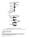
F. Slide stainless steel seal retainer in plastic sleeve until ‘‘running’’ O-ring No. 3 is just covered by plastic
sleeve, as shown in View B of Figure 8.
G. Carefully place shaft seal assembly over beater drive shaft and locate slots of seal retainer on drive
shaft pin. Then, carefully and simultaneously, push and turn plastic sleeve to locate locking tabs on
sleeve in notches of freeze cylinder retainer. When tabs are seated in notches, press assembly firmly
in place.
H. Position SCRAPER BLADES (item 2) on BEATER (item 13) as shown in Figure 3. Slide beater into
freeze cylinder so slotted hooks engage DRIVE PIN (item 17) on DRIVE SHAFT (item 24). Turn
beater to the right (clockwise) to lock in place.
I. Lubricate O-RING (item 5) with water to facilitate faceplate installation. Position O-RING (item 5) on
FACEPLATE (item 8). Install faceplate on Unit so dispensing valve spout faces down. Tighten hex
nuts until faceplate touches freeze cylinder all around flange. CAUTION - DO NOT OVERTIGHTEN
HEX NUTS.