


326142000 2
Table 1. Design Data (cont’d)
Table 1. Design Data (cont’d)
Overall Dimensions: Overall Dimensions:
Height 60-1/2 inches
Width 19-1/4 inches
Depth Without Drip Tray 32-1/2 inches
Depth With Drip Tray 38 inches
Shipping Weight (approx.) 466 pounds
Compressor Horsepower 2 H.P.
Refrigeration System: Refrigeration System:
Refrigerant Type R-502
Refrigerant Charge See Unit Nameplate
Ambient Operating Temperature 40° F to 100° F
Electrical Requirements: Electrical Requirements:
60 Hz Unit:
Operating Voltage 219/242 VAC60 Hz Single Phase
Current Draw 21.2 Amps
50 Hz Unit:
Operating Voltage 219/242 VAC 50 Hz Single
Phase
Current Draw 22 Amps
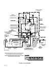
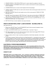
THEORY OF OPERATION
(see Figure 2)
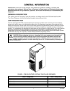
IMPORTANT: Before connecting electrical power to Unit, refer to nameplate and note if Unit is to be
operated with 50 or 60 Hz power source and also note beaters drive motors manufacturer’s name. No.
6, No. 7, and No. 8 switches on DIP switch assembly on master circuit board must be set according to
motors manufacturer and for 50 or 60 Hz operation.
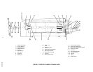
A CO2 cylinder delivers carbon dioxide (CO
2
) gas to an adjustable primary CO
2
regulator assembly attached to
the cylinder. Primary CO
2
regulator assembly in turn delivers CO
2
gas to adjustable secondary CO
2
regulators
inside the Unit and also to two soft drink tanks. CO
2
is delivered from adjustable secondary CO
2
regulators to
carbonator tank and also two product-blender tanks inside the Unit. CO
2
gas pressure pushes syrup out of soft
drink tanks, through syrup sold-out float switches, through electrically-operated syrup solenoid valves, through
adjustable syrup flow regulators, and on to product blender tanks. At the same time, plain water passes through
water pressure regulator and is pumped into carbonator tank by water pump and is carbonated by CO
2
gas
pressure also entering tank. Carbonated water is pushed by CO
2
gas pressure from carbonator tank, through
electrically operated carbonated water solenoid valves through adjustable carbonated water flow regulators, and
on to product blender tanks. Carbonated water and syrup enter tanks properly proportioned (blended) for
desired BRIX of dispensed product by adjustment of syrup flow regulators. From product blender tanks, product
is pushed by CO
2
gas into freeze cylinders. The beater in each freeze cylinder is driven by an electric motor.
Scraper blades, attached to beaters, scrapes product from cylinder walls as product enters freeze cylinders and
is frozen. Transparent faceplate, attached to front of each freeze cylinder, includes a self-closing dispensing
valve and a spring-loaded relief valve that protects freeze cylinder from accidental over pressure. The relief
valve is also used to bleed CO
2
gas pressure from freeze cylinder to atmosphere when filling cylinder with
product. Electronic sensing on each freeze cylinder motor provides a means of adjusting viscosity (consistency)
of dispensed product to suit customer preference.
DEFROST SYSTEMS
The Unit is equipped with both manual and automatic hot-gas defrost systems. The automatic defrost system
may be programmed into Unit to occur up to nine different times a day with a minimum of two hours between
defrost time settings or the system may be completely turned off.