


56
326142000
2. Sanitize syrup system as instructed in CLEANING AND SANITIZING.
REPLACING FREEZE CYLINDER BEATER MOTOR
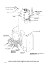
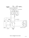
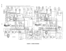
(see Figure 6 and 14 )
NOTE: Use Beater Drive Shaft Assembly Alignment Tool Kit (P/N 0726) when installing beater drive
shaft assembly.
1. Press ‘‘OFF 1’’ and ‘‘OFF 2’’ control switches to stop refrigeration system and beaters motors.
2. Disconnect electrical power from Unit.
3. Remove back and side panels as instructed.
4. Tag beater drive motor electrical wiring for identification, then disconnect wiring from motor terminal block
on Unit frame.
5. Remove hex nuts and lockwashers securing beater drive motor to Unit frame.
6. Very carefully, remove old beater drive motor from Unit. BE CAREFUL NOT TO LOSE PLASTIC
COUPLER LOCATED BETWEEN BEATER DRIVE MOTOR SHAFT COUPLING AND BEATER DRIVE
SHAFT ASSEMBLY COUPLING.
7. Very carefully, pull old beater drive motor out of Unit. BE CAREFUL NOT TO LOSE PLASTIC COUPLER
LOCATED BETWEEN BEATER DRIVE MOTOR SHAFT COUPLING AND BEATER DRIVE SHAFT
ASSEMBLY COUPLING.
8. Note how far beater drive motor shaft protrudes inside coupling. Using allen wrench, loosen allen head
setscrew in coupling, then remove coupling from motor shaft.
9. Install coupling on new beater drive motor shaft, then tighten allen head setscrew securely. MAKE SURE
COUPLING IS INSTALLED ON MOTOR SHAFT SAME DISTANCE AS NOTED IN STEP 8 preceding.
CAUTION: The new beater drive motor is provided with a gear box vent that is plugged with
a hex-Socket plug to prevent oil from leaking out of the gear box. After beater drive motor
has been installed, remove hex-socket plug and install vent plug loose-shipped with beater
drive motor.
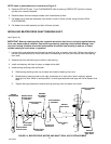
10. Determine which beater drive motor gear box vent hole will be in ‘‘up’’ position when motor is in installed
position.
11. Remove hex-socket plug from vent hole and install loose-shipped vent plug. DO NOT LAY MOTOR IN
POSITION THAT WILL ALLOW OIL TO LEAK OUT OF GEAR BOX THROUGH VENT PLUG.
12. Place plastic power coupler in beater drive motor shaft coupling. TAPE POWER COUPLER TO MOTOR
SHAFT COUPLING TO PREVENT COUPLER FROM FALLING OUT DURING INSTALLATION OF
MOTOR IN UNIT.
13. Very carefully, slide beater drive motor shaft through hole in Unit frame up to coupling on end of beater
drive shaft assembly.
14. Engage plastic coupler, on end of beater drive motor shaft, in coupling on end of beater drive shaft
assembly.
15. Secure beater drive motor to Unit frame with bolts and lockwashers.
16. Connect electrical wiring to beater drive motor terminals, then install access cover plate on motor.
17. Install back and side panels.
18. Connect electrical power to Unit.
19. Press ‘‘AUTO BLEND 1’’ and ‘‘AUTO BLEND 2’’ control switches, then press ‘‘AUTO 1’’ and ‘‘AUTO 2’’
switches to start freeze cylinders beaters and refrigeration system.