


36326142000
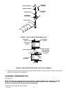
1. Remove Unit front lower access panel as instructed for access to carbonator secondary CO
2
regulator with
100-psi gage.
2. Observe pressure setting on carbonator secondary CO
2
regulator gage.
3. To lower CO
2
pressure, loosen regulator adjusting screw lock nut. Turn adjusting screw to the left
(counterclockwise) until pressure gage reads 15-psi below desired reading, then turn screw to the right
(clockwise) until gage reads desired pressure. DO NOT SET CO
2
REGULATOR PRESSURE BELOW
25-PSI HIGHER THAN PRODUCT BLENDER TANKS CO
2
REGULATORS ARE ADJUSTED TO (SEE
PRECEDING IMPORTANT NOTE). Tighten adjusting screw lock nut after each adjustment.
4. To raise CO
2
pressure, turn regulator adjusting screw to the right (clockwise) until gage reads desired
pressure. DO NOT SET PRESSURE HIGHER THAN 60-PSI. Make sure primary CO
2
regulator on CO
2
cylinder is set at 80 to 100-psi. Tighten adjusting screw lock nut after each adjustment.
5. Install Unit front lower access panel by reversing removal procedure.
ADJUSTING BEATER MOTOR CURRENT (EITHER SIDE)
Adjusting beater motor current (either side) procedure is very important and must be performed as instructed.
Be sure you fully understand the instructions before performing the current adjustments or doing any
preventative maintenance current readings check.
Any current adjustments or preventative maintenance current readings check on the beater motor current
(either side) must be performed with both freeze cylinders fully defrosted. A partially defrosted freeze cylinder
will cause false current readings to be displayed on the message display. Adjust beater motor current (either
side) as follows:
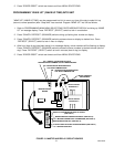
1. Place No. 4 ‘‘BEATER MOTOR CURRENT READOUT’’ switch on DIP SWITCH assembly on master
circuit board (see Figure 10) in ‘‘ON’’ position. Both freeze cylinders beater motors will start and operate
and beaters motors current ratings will be displayed on message display.
2. Display should be adjusted to read A150 B150 ± 2 by adjusting MOTOR CURRENT ADJUSTMENTS
located on No. 1 and No. 2 relay circuit boards (see Figure 10). These figures will fluctuate slightly with
variations in line voltage and motor loads.
3. After completion of adjusting beater motor current to A150B150 ± 2, make sure No. 5 ‘‘MOTOR CURRENT
SELF-CALIBRATION’’ switch on DIP SWITCH assembly on master circuit board (see Figure 10) is in
‘‘OFF’’ position. No. 5 switch in ‘‘OFF’’ position allows the ‘‘MOTOR CURRENT’’ SELF-CALIBRATION’’
electronics to automatically self calibrate the beaters motors currents at completion of each defrost cycle.
CAUTION: IF NO. 4 ‘‘BEATER MOTOR CURRENT READOUT’’ SWITCH ON DIP SWITCH
assembly is placed in ‘‘ON’’ position and beater motor current readings were A155B145 and
switch was then placed back in ‘‘OFF’’ position without readjusting to A150B150 ± 2, beater
motor current has just been reset at A155B145. Operating the FCB Dispenser at these current
readings may have serious effects on its operation.
ANY TIME THE NO. 4 ‘‘BEATER MOTOR CURRENT READOUT’’ SWITCH ON DIP SWITCH ASSEMBLY IS
PLACE IN ‘‘ON’’ POSITION, THE BEATER MOTOR CURRENT READINGS MUST BE READJUSTED TO
A150B150 ± 2 AS INSTRUCTED, THEN SWITCH MUST BE PLACE BACK IN THE ‘‘OFF’’ POSITION.
ADJUSTMENTS, AND PROGRAMMING MAIN MENU SELECTIONS INTO
UNIT
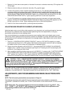
NOTE: The Unit control panel switches are as shown in Figure 9.
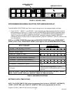
The following instructions outline adjustments and programming main menu selections, components
‘‘DIAGNOSE’’ (DIAGNOSTIC MODE), and ‘‘TOTALS’ (DISPLAYED CYCLES AND HOURS TOTALS) into the
Unit.
NOTE: Plain water, CO
2
and syrup supplies to Unit must be satisfied to turn off ‘‘H
2
O OUT’’, ‘‘CO
2
OUT’’, ‘‘SYRUP 1’’, and ‘‘SYRUP 2’’ fault messages on message display before adjustments and
programming procedures can be performed on the Unit.