


9 326142000
1. Close to a plain water inlet supply line with a minimum pressure of 12-psig.
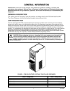
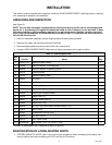
NOTE: Circulating air, required to cool the refrigeration system’s condenser coil, is drawn in through
grille on front and exhausted out through sides and back of Unit. Restricting air circulation through the
Unit will decrease its cooling efficiency.
2. When installing Unit, do not allow obstruction to block grille on front which will block off air intake to inside
of Unit. If installation dictates only one side or back being unobstructed, allow 18-inches clearance between
Unit and obstruction. If both sides or one side and back are unobstructed, allow 12-inches clearance. If
both sides and back are unobstructed, allow 6-inches clearance.
INSTALLING UNIT
PLACING UNIT IN OPERATING LOCATION
1. Place Unit in operating location meeting requirements of SELECTING LOCATION.
2. After Unit has been placed in operating location, make sure front (dispensing valve side) is 1/4 to 3/8-inch
higher than the back to eliminate gas pockets being trapped inside the freeze cylinders.
3. To comply with National Sanitation Foundation (NSF) requirements, Unit installed with base contacting floor
must have base sealed to floor with Dow Corning RTV 731 or equivalent.
INSTALLING DRIP TRAY SUPPORTS, DRIP TRAY, AND CUP REST
1. Install DRIP TRAY SUPPORTS (item 8) on panel above lower front access panel on front of Unit. Secure
supports to panel with THREAD CUTTING SCREWS (item 9).
2. Place DRIP TRAY (item 7) in FRAME, DRIP TRAY (item 13), then slide frame up on drip tray supports on
front of Unit.
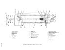
INSTALLING DRIP TRAY DRAIN KIT (ITEM 14)
(see Figure 5)
1. Drill 5/8-inch diameter hole in lowest point (center) in bottom of drip tray.
2. Install DRAIN FITTING (item 15) in drip tray and secure with LOCKWASHER, INTERNAL TOOTH (item
16) and HEX NUT, 5/8-32 (item 17).
3. Push DRAIN HOSE (item 17) over drip tray fitting and secure with DRAIN HOSE CLAMP (item 18).
NOTE: Drip tray drain hose may be routed to a waste container, but is not recommended due to
sanitation and cleaning problems. Connection of drain hose to a permanent drain is most highly
recommended.
4. Route drip tray drain hose to and connect to permanent drain.
5. Place CUP REST (item 6) in drip tray.
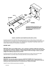
INSTALLING PRIMARY CO
2
REGULATOR ASSEMBLY ON CO
2
CYLINDER
(see Figure 2)
WARNING: To avoid personal injury and/or property damage, always secure CO
2
cylinder in
upright position with a safety chain to prevent it from falling over. Should the valve become
accidentally damaged or broken off, CO
2
cylinder can cause serious personal injury.