


55 326142000
INSTALLING BEATER DRIVE SHAFT ASS’Y AND BEATER DRIVE MOTOR ON UNIT
NOTE: Use Beater Drive Shaft Assembly Alignment Tool Kit (P/N 0726) when installing beater drive
shaft assembly.
1. Lubricate beater drive shaft bearing boot with DOW-CORNING DC-111 (P/N 321471000) light grade
silicone lubricant.
2. Install beater drive shaft assembly in freeze cylinder.
3. Place plastic power coupler in beater drive motor shaft coupling. TAPE POWER COUPLER TO MOTOR
SHAFT COUPLING TO PREVENT COUPLER FROM FALLING OUT DURING INSTALLATION OF
MOTOR IN UNIT.
4. Very carefully, slide beater drive motor shaft through hole in Unit frame up to coupling on end of beater
drive shaft assembly.
5. Engage plastic coupler, on end of beater drive motor shaft, in coupling on end of beater drive shaft
assembly.
6. Secure beater motor to Unit frame with bolts and lockwashers.
7. Connect electrical wiring to beater drive motor terminals, then install access cover plate on motor.
8. Refer to DISPENSING VALVES CAGED O-RINGS AND BEATER DRIVE SHAFTS SEALS ASSEMBLIES
under LUBRICATION and perform procedure to lubricate beater drive shaft seal assembly.
9. Carefully place shaft seal assembly over beater drive shaft and locate slots of seal retainer on drive shaft
pin. Then, carefully and simultaneously push and turn plastic sleeve in notches of freeze cylinder retainer.
When tabs are seated in notches, press assembly firmly in place.
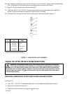
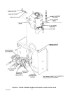
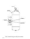
10. Install beater shaft and scraper blades in freeze cylinder (see Figure 4).
11. Lubricate faceplate O-ring with water to facilitate installation, then install faceplate on Unit. Secure
faceplate with hex nuts and lockwashers. DO NOT OVERTIGHTEN HEX NUTS.
RESTORING UNIT OPERATION
1. Open product shutoff valve leading from product blender tank to freeze cylinder.
2. Connect electrical power to Unit.
3. Sanitize syrup system as instructed in CLEANING AND SANITIZING.
4. Press ‘‘AUTO BLEND 1’’ and ‘‘AUTO BLEND 2’’ to begin filling freeze cylinder. Open freeze cylinder
faceplate relief valve to bleed air from cylinder while filling with product, then close valve. Do not relieve
freeze cylinder pressure too fast or product will foam excessively in cylinder and lose carbonation.
5. Press ‘‘AUTO 1’’ and ‘‘AUTO 2’’ switches to start freeze cylinder and refrigeration system.
6. Check for leaks and repair if evident.
7. Install back and side panels by reversing removal procedure.
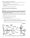
REPLACING BEATER DRIVE SHAFT SEAL ASS’Y
(see Figures 3 and 14)
1. Refer to DISPENSING VALVES CAGED O-RINGS AND BEATER DRIVE SHAFTS SEALS ASSEMBLIES
under LUBRICATION for instructions to replace beater drive shaft seal assembly.