


17
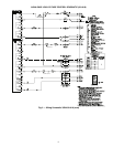
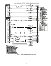
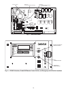
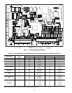
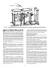
Energy Management Module (Fig. 11) —
This
factory-installed option (FIOP) or field-installed accessory is
used for the following types of temperature reset, demand
limit, and/or ice features:
• 4 to 20 mA leaving fluid temperature reset (requires
field-supplied 4 to 20 mA generator)
• 4 to 20 mA cooling set point reset (requires field-
supplied 4 to 20 mA generator)
• Discrete inputs for 2-step demand limit (requires field-
supplied dry contacts capable of handling a 24 vac,
50 mA load)
• 4 to 20 mA demand limit (requires field-supplied 4 to
20 mA generator)
• Discrete input for Ice Done switch (requires field-
supplied dry contacts capable of handling a 24 vac,
50 mA load)
See Demand Limit and Temperature Reset sections on
pages 44 and 43 for further details.
Loss-of-Cooler Flow Protection —
A proof-of-cooler
flow device is factory installed in all chillers. It is recommended
that proper operation of the switch be verified on a regular basis.
Thermostatic Expansion Valves (TXV) —
All units
are equipped from the factory with conventional TXVs. Each
refrigeration circuit is also supplied with a factory-installed
liquid line filter drier and sight glass.
The TXV is set at the factory to maintain approximately 8 to
12° F (4.4 to 6.7° C) suction superheat leaving the cooler by
metering the proper amount of refrigerant into the cooler. All
TXVs are adjustable, but should not be adjusted unless
absolutely necessary.
The TXV is designed to limit the cooler saturated suction
temperature to 55 F (12.8 C). This makes it possible for unit to
start at high cooler fluid temperatures without overloading the
compressor.
Capacity Control —
The control system cycles com-
pressors, and minimum load valve solenoids (if equipped) to
maintain the user-configured leaving chilled fluid temperature
set point. Entering fluid temperature is used by the Main Base
Board (MBB) to determine the temperature drop across the
cooler and is used in determining the optimum time to add or
subtract capacity stages. The chilled fluid temperature set point
can be automatically reset by the return fluid temperature,
space, or outdoor-air temperature reset features. It can also be
reset from an external 4 to 20-mA signal (requires Energy
Management Module FIOP or accessory).
The control has an automatic lead-lag feature built in which
determines the wear factor (combination of starts and run
hours) for each compressor. If all compressors are off and less
than 30 minutes has elapsed since the last compressor was
turned off, the wear factor is used to determine which compres-
sor to start next. If no compressors have been running for more
than 30 minutes and the leaving fluid temperature is greater
than the saturated condensing temperature, the wear factor is
still used to determine which compressor to start next. If the
leaving fluid temperature is less than the saturated condensing
temperature, then the control will start either compressor A1 or
compressor B1 first, depending on the user-configurable circuit
lead-lag value.
The TXVs will provide a controlled start-up. During start-
up, the low pressure logic will be bypassed for 2
1
/
2
minutes to
allow for the transient changes during start-up. As additional
stages of compression are required, the processor control will
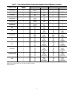
add them. See Table 6 and 7.
If a circuit is to be stopped, the compressor with the lowest
wear factor will be shut off first in most cases. Certain override
conditions may shut off the smaller of two compressors on a
circuit first.
The capacity control algorithm runs every 30 seconds. The
algorithm attempts to maintain the Control Point at the desired
set point. Each time it runs, the control reads the entering and
leaving fluid temperatures. The control determines the rate at
which conditions are changing and calculates 2 variables based
on these conditions. Next, a capacity ratio is calculated using
the 2 variables to determine whether or not to make any
changes to the current stages of capacity. This ratio value
ranges from –100 to +100%. If the next stage of capacity is a
compressor, the control starts (stops) a compressor when the
ratio reaches +100% (–100%). If installed, the minimum load
valve solenoid will be energized with the first stage of capacity.
Minimum load valve value is a fixed 30% in the total capacity
calculation. The control will also use the minimum load valve
solenoid as the last stage of capacity before turning off the last
compressor. If the close control feature (CLS.C) [Configura-
tion, OPT2] is enabled the control will use the minimum load
valve solenoid whenever possible to fine tune leaving fluid
temperature control. A delay of 90 seconds occurs after each
capacity step change. Refer to Tables 6 and 7.
Care should be taken when interfacing with other manufac-
turer’s control systems due to possible power supply
differences, full wave bridge versus half wave rectification.
The two different power supplies cannot be mixed.
ComfortLink™ controls use half wave rectification. A
signal isolation device should be utilized if a full wave
bridge signal generating device is used.
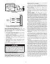
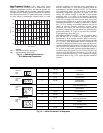
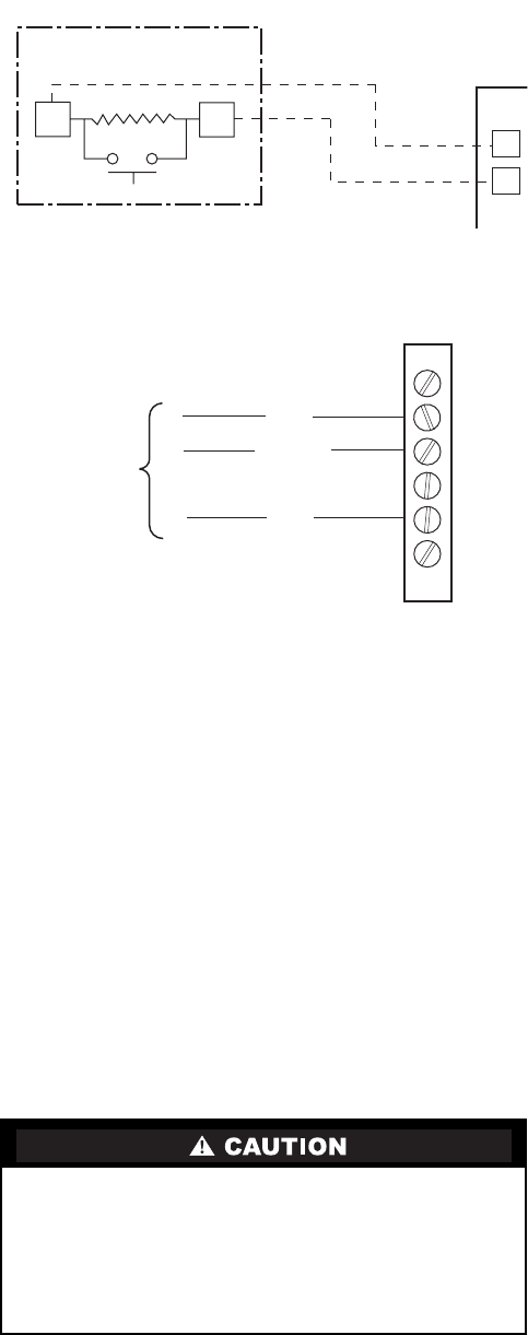
SPT (T10) PART NO. 33ZCT55SPT
SENSOR
SEN
SEN
TB5
5
6
Fig. 9 — Typical Space Temperature
Sensor Wiring
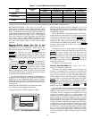
T-55 SPACE
SENSOR
SCN+
SCN GND
SCN-
TO SCN
COMM 1
BUS (PLUG)
AT UNIT
1
2
3
4
5
6
Fig. 10 — SCN Communications Bus Wiring
to Optional Space Sensor RJ11 Connector