


3
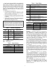
Table 1 — Unit Sizes
*60 Hz only.
†50 Hz only.
MAJOR SYSTEM COMPONENTS
General —
The 30RA air-cooled reciprocating chillers
contain the ComfortLink™ electronic control system that
controls and monitors all operations of the chiller.
The control system is composed of several components as
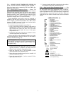
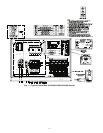
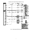
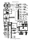
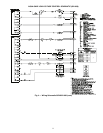
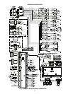
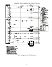
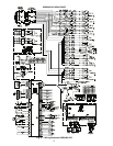
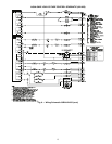
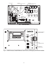
listed in the sections below. See Fig. 1 and 2 for typical control
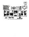
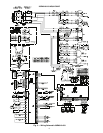
box drawing. See Fig. 3-6 for control schematics.
Main Base Board (MBB) —
See Fig. 7. The MBB is
the heart of the ComfortLink control system. It contains the
major portion of operating software and controls the operation
of the machine. The MBB continuously monitors input/output
channel information received from its inputs and from all other
modules. The MBB receives inputs from the discharge and
suction pressure transducers and thermistors. See Table 2. The
MBB also receives the feedback inputs from each compressor
contactor, auxiliary contacts, and other status switches. See
Table 3. The MBB also controls several outputs. Relay outputs
controlled by the MBB are shown in Table 4. Information
is transmitted between modules via a 3-wire communication
bus or LEN (Local Equipment Network). The SCN (Sterlco
Comfort Network) bus is also supported. Connections to both
LEN and SCN buses are made at TB3. See Fig. 8.
Scrolling Marquee Display —
This standard device
is the keypad interface used for accessing chiller information,
reading sensor values, and testing the chiller. The marquee
display is a 4-key, 4-character, 16-segment LED (light-emitting
diode) display. Eleven mode LEDs are located on the display
as well as an Alarm Status LED. See Marquee Display Usage
section on page 23 for further details.
Energy Management Module (EMM) —
The EMM
module is available as a factory-installed option or as a field-
installed accessory. The EMM module receives 4 to 20 mA
inputs for the leaving fluid temperature reset, cooling set point
and demand limit functions. The EMM module also receives
the switch inputs for the field-installed 2-stage demand limit
and ice done functions. The EMM module communicates the
status of all inputs with the MBB, and the MBB adjusts the
control point, capacity limit, and other functions according to
the inputs received.
Enable/Off/Remote Contact Switch —
The Enable/
Off/Remote Contact switch is a 3-position switch used to
control the chiller. When switched to the Enable position the
chiller is under its own control. Move the switch to the Off
position to shut the chiller down. Move the switch to the
Remote Contact position and a field-installed dry contact can
be used to start the chiller. The contacts must be capable of
handling a 24 vac, 50-mA load. In the Enable and Remote
Contact (dry contacts closed) positions, the chiller is allowed to
operate and respond to the scheduling configuration, SCN
configuration and set point data. See Fig. 8.
Emergency On/Off Switch —
The Emergency On/Off
switch should only be used when it is required to shut the
chiller off immediately. Power to the MBB, EMM, and
marquee display is interrupted when this switch is off and all
outputs from these modules will be turned off.
Board Addresses —
The Main Base Board (MBB) has
a 3-position Instance jumper that must be set to ‘1.’ All other
boards have 4-position DIP switches. All switches are set to
‘On’ for all boards.
Control Module Communication
RED LED — Proper operation of the control boards can be
visually checked by looking at the red status LEDs
(light-emitting diodes). When operating correctly, the red status
LEDs should be blinking in unison at a rate of once every
2 seconds. If the red LEDs are not blinking in unison, verify
that correct power is being supplied to all modules. Be sure that
the Main Base Board (MBB) is supplied with the current
software. If necessary, reload current software. If the problem
still persists, replace the MBB. A red LED that is lit continu-
ously or blinking at a rate of once per second or faster indicates
that the board should be replaced.
GREEN LED — The MBB has one green LED. The Local
Equipment Network (LEN) LED should always be blinking
whenever power is on. All other boards have a LEN LED
which should be blinking whenever power is on. Check LEN
connections for potential communication errors at the board J3
and/or J4 connectors. Communication between modules is
accomplished by a 3-wire sensor bus. These 3 wires run in
parallel from module to module. The J4 connector on the MBB
provides both power and communication directly to the
marquee display only.
YELLOW LED — The MBB has one yellow LED. The
Sterlco Comfort Network (SCN) LED will blink during times
of network communication.
Sterlco Comfort Network (SCN) Interface —
The 30RA chiller units can be connected to the SCN if
desired. The communication bus wiring is a shielded,
3-conductor cable with drain wire and is supplied and installed
in the field. See Table 5. The system elements are connected to
the communication bus in a daisy chain arrangement. The
positive pin of each system element communication connector
must be wired to the positive pins of the system elements on
either side of it. This is also required for the negative and
signal ground pins of each system element. Wiring connections
for SCN should be made at TB3. Consult the SCN Contrac-
tor’s Manual for further information.
NOTE: Conductors and drain wire must be 20 AWG (Ameri-
can Wire Gage) minimum stranded, tinned copper. Individual
conductors must be insulated with PVC, PVC/nylon, vinyl,
Teflon, or polyethylene. An aluminum/polyester 100% foil
shield and an outer jacket of PVC, PVC/nylon, chrome vinyl,
or Teflon with a minimum operating temperature range of
–20 C to 60 C is required. Wire manufactured by Alpha (2413
or 5463), American (A22503), Belden (8772), or Columbia
(02525) meets the above mentioned requirements.
It is important when connecting to a SCN communication
bus that a color coding scheme be used for the entire network
to simplify the installation. It is recommended that red be used
for the signal positive, black for the signal negative, and white
for the signal ground. Use a similar scheme for cables contain-
ing different colored wires.
UNIT
NOMINAL CAPACITY
(TONS) 50/60 Hz
30RA010
10/10
30RA015
14/13
30RA018
16/16
30RA022
22/20
30RA025
24/23
30RA030*
27
30RA032†
30
30RA035
35/34
30RA040*
38
30RA042†
40
30RA045
43/45
30RA050*
47
30RA055*
54