


74
MAINTENANCE
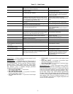
Recommended Maintenance Schedule —
The fol-
lowing are only recommended guidelines. Jobsite conditions
may dictate that maintenance schedule is performed more often
than recommended.
Routine:
For machines with E-coat Condenser Coils:
• Check condenser coils for debris, clean as necessary
with Sterling approved coil cleaner.
• Periodic clean water rinse, especially in coastal and
industrial applications.
Every month:
• Check condenser coils for debris, clean as necessary
with Sterling approved coil cleaner.
• Check moisture indicating sight glass for possible refrig-
erant loss and presence of moisture.
Every 3 months (for all machines):
• Check refrigerant charge.
• Check all refrigerant joints and valves for refrigerant
leaks, repair as necessary.
• Check chilled water flow switch operation.
• Check condenser coils for debris, clean as necessary
with Sterling approved coil cleaner.
• Check all condenser fans for proper operation.
• Check compressor oil level.
• Check crankcase heater operation.
Every 12 months (for all machines):
• Check all electrical connections, tighten as necessary.
• Inspect all contactors and relays, replace as necessary.
• Check accuracy of thermistors, replace if greater than
± 2° F (1.2° C) variance from calibrated thermometer.
• Obtain and test an oil sample. Change oil only if
necessary.
• Check to be sure that the proper concentration of anti-
freeze is present in the chilled water loop, if applicable.
• Verify that the chilled water loop is properly treated.
• Check refrigerant filter driers for excessive pressure
drop, replace as necessary.
• Check chilled water strainers, clean as necessary.
• Check cooler heater operation, if equipped.
• Check condition of condenser fan blades and that they
are securely fastened to the motor shaft.
• Perform Service Test to confirm operation of all
components.
• Check for excessive cooler approach (Leaving Chilled
Water Temperature — Saturated Suction Temperature)
which may indicate fouling. Clean cooler vessel if
necessary.
PRE-START-UP
Do not attempt to start the chiller until following checks
have been completed.
System Check
1. Check all auxiliary components, such as chilled fluid
pumps, air-handling equipment, or other equipment to
which the chiller supplies liquid. Consult manufacturer's
instructions. Verify that any pump interlock contacts have
been properly installed. If the unit If the unit has
field-installed accessories, be sure all are properly in-
stalled and wired correctly. Refer to unit wiring diagrams.
2. Use the Scrolling Marquee display to adjust the Cooling
Set Point.
3. Fill chilled fluid circuit with clean water (with recom-
mended inhibitor added) or other non-corrosive fluid to
be cooled. Bleed all air out of the high points of the sys-
tem. If chilled water is to be maintained at a temperature
below 40 F (4.4 C) or outdoor temperatures are expected
to be below 32 F (0° C), a brine of sufficient concentra-
tion must be used to prevent freeze-up at anticipated
suction temperatures. See Table 40.
4. Check tightness of all electrical connections.
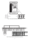
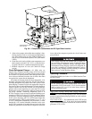
5. Oil should be visible in the compressor sightglass(es).
See Fig. 39. An acceptable oil level in the compressors is
from ¼ to ¾ of sight glass. Adjust the oil level as re-
quired. See Check Oil Charge section on page 60 for
Sterling approved oils.
6. Electrical power source must agree with unit nameplate.
7. All condenser fan and factory installed hydronic package
pump motors are three phase. Check for proper rotation
of condenser fans first BEFORE attempting to start
pumps or compressors. To reverse rotation, interchange
any two of the main incoming power leads.
8. Be sure system is fully charged with refrigerant (see
Check Refrigerant Charge section on page 75).
9. If unit is a brine unit, check to ensure proper brine con-
centration is used to prevent freezing.
10. Verify proper operation of cooler and hydronic package
heaters (if installed). Heaters operate at the same voltage
as the main incoming power supply and are single phase.
Heater current is approximately .4 amps for 380, 400, 460
and 575 v units. Heater current is approximately .8 amps
for 230 v units.
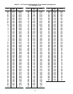
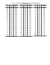
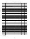
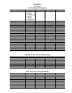
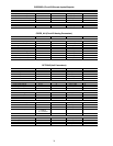
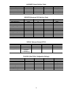
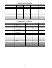
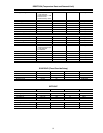
Table 40 — Minimum Cooler Flow Rates and
Minimum Loop Volume
START-UP AND OPERATION
NOTE: Refer to Start-Up Checklist on pages CL-1 to CL-8.
Actual Start-Up —
Actual start-up should be done only
under supervision of a qualified refrigeration mechanic.
1. Be sure all service valves are open.
2. Using the Scrolling Marquee display, set leaving-fluid set
point (CSP.1) [Set Point, COOL]. No cooling range ad-
justment is necessary.
3. Start chilled fluid pump (if not configured for cooler
pump control).
4. Turn ENABLE/OFF/REMOTE CONTACT switch to
ENABLE position.
IMPORTANT: Before beginning Pre-Start-Up or Start-Up,
complete Start-Up Checklist for 30RA Liquid Chiller at
end of this publication (page CL-1 to CL-8). The Checklist
assures proper start-up of a unit, and provides a record of
unit condition, application requirements, system informa-
tion, and operation at initial start-up.
UNIT SIZE
30RA
COOLER MINIMUM
FLOW
MINIMUM COOLER
LOOP VOLUME
Gpm L/s Gal. L
010
12 .76 40 151.2
015
16 1.01 55 207.9
018
19 1.20 48 181.4
022
26 1.64 65 245.7
025
29 1.83 71 268.3
030
33 2.08 82 309.3
035
42 2.65 102 393.1
040
45 2.80 113 449.8
042
48 3.02 119 427.1
045
52 3.28 129 487.6
050
57 3.59 142 536.6
055
65 4.10 163 616.1