


51
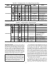
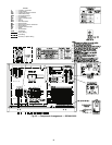
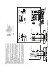
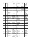
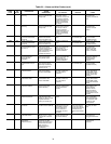
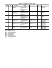
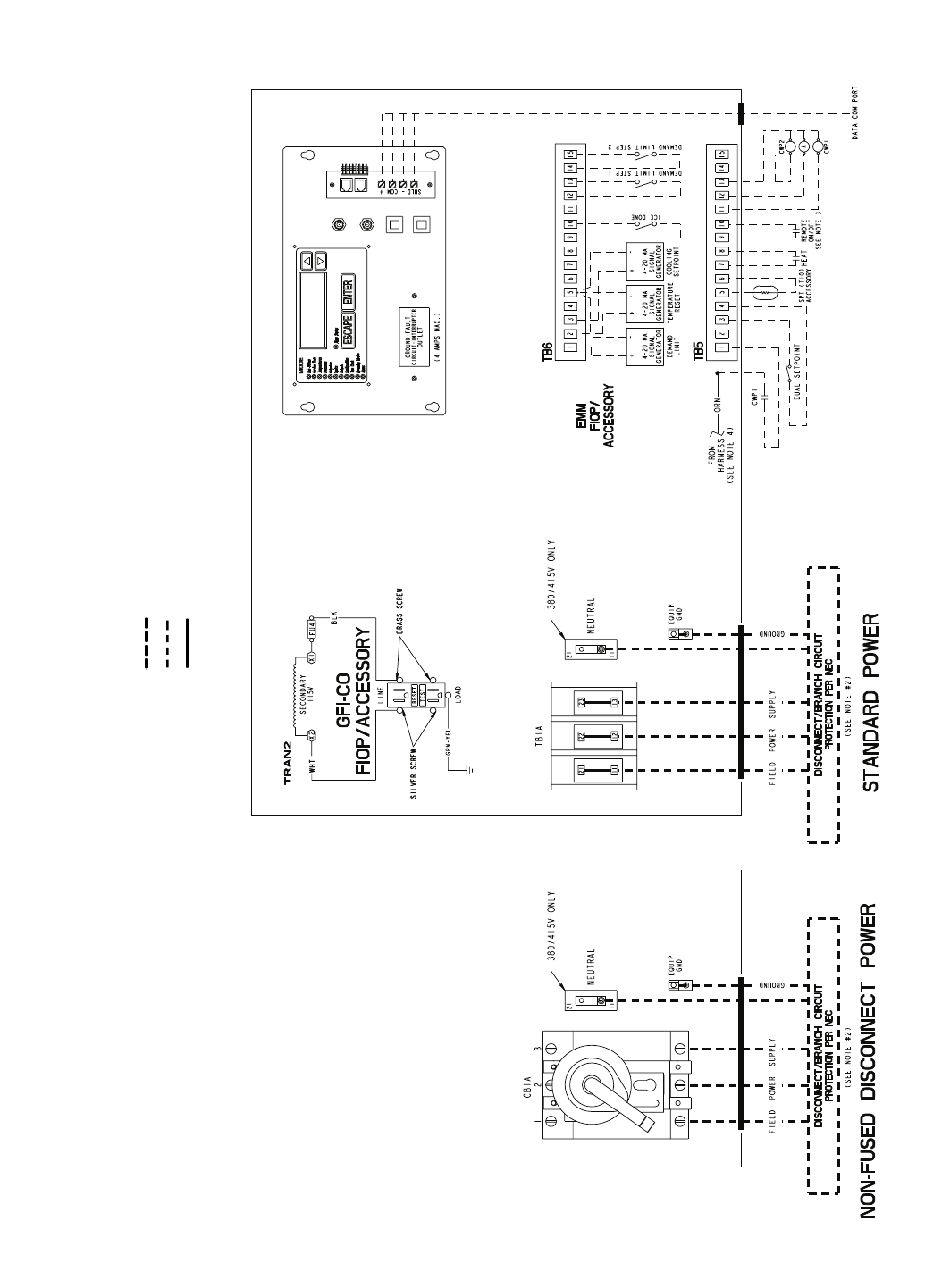
Fig. 25 — Control and Field Power Wiring Diagram — 30RA010-030
NOTES:
1. Factory wiring is in accordance with UL 1995 standards. Field modifications
or additions must be in compliance with all applicable codes.
2. Wiring for main field supply must be rated 75 C minimum. Use copper for all
units. Maximum incoming wire size for the terminal block is #2/0 AWG. Max-
imum incoming wire size for 60 and 100 amp non-fused disconnect is
#1 AWG. Maximum incoming wire size for 250 amp non-fused disconnect is
350 kcmil.
3. Terminals 9 and 10 of TB5 are for field external connections for remote on-
off. The contacts must be rated for dry circuit application capable of handling
a 24 vac load up to 50 mA.
4. Terminals 1 and 2 of TB5 are connected to the factory-installed chilled water
flow switch (CWFS). To add chilled water pump interlock contacts, remove
the orange harness wire from TB5-1 and wire contacts in series as shown.
The contacts must be rated for dry circuit application capable of handling a
24 vac load up to 50 mA.
5. Terminals 11 and 13 of TB5 are for control of chilled water pump 1 (CWP1)
starter. Terminals 13 and 15 of TB5 are for control of chilled water pump 2
(CWP2) starter. The maximum load allowed for the chilled water pump relay
is 5 va sealed, 10 va inrush at 24 v. Field power supply is not required.
6. Terminals 12 and 13 of TB5 are for an alarm relay. The maximum load
allowed for the alarm relay is 5 va sealed, 10 va inrush at 24 v. Field power
supply is not required.
7. Make appropriate connections to TB6 as shown for energy management
board options. The contacts for demand limit and ice done options must be
rated for dry circuit application capable of handling a 24 vac load up to
50 mA.
8. Care should be taken when interfacing with other manufacturer’s control
systems due to possible power supply differences: full wave bridge versus
half wave rectification. The two different power supplies cannot be mixed.
Comfort
Link™ controls use half wave rectification. A signal isolation device
should be utilized if a full wave bridge signal generating device is used.
LEGEND
A — Alarm
CWPI — Chilled Water Pump Interlock
CWP — Chilled Water Pump
EMM — Energy Management
FIOP — Factory-Installed Option
NEC — National Electrical Code
SPT — Space Temperature
TB — Terminal Block
Field Power Wiring
Field Control Wiring
Factory-Installed Wiring